
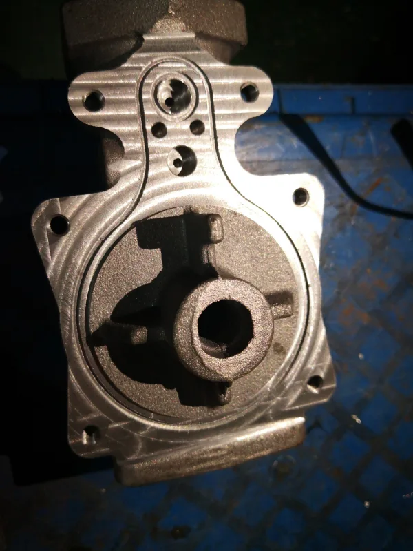
Faced with the pressure to reduce weight brought about by the transition to electrification, sand casting—with its advantages of low mold costs and design flexibility—is becoming the preferred manufacturing method for large aluminum structural components such as subframes and battery trays. This article describes a comprehensive aluminum sand casting design guide, covering the matching of CT grades for casting tolerances, the planning of draft angles and parting lines, and the verification of flowability for minimum wall thicknesses. In actual production, by utilizing resin sand technology and controlling the pouring temperature between 700–740°C, it is possible to consistently achieve CT Grade 7–8 precision while avoiding cold shuts in thin-walled sections. These design guidelines are driving the expansion of sand casting into the production of high-performance electric vehicle components. The following sections will provide an in-depth analysis of how each parameter balances weight reduction with structural reliability, helping to avoid common casting defects.
Introduction to sand casting for lightweight automotive components
Modern automotive engineering increasingly relies on sand casting to strike a balance between structural integrity and stringent vehicle weight reduction targets. As Tier 1 suppliers and automakers transition to electrified platforms, this traditional yet highly mature manufacturing process offers great flexibility in casting complex, large components without the massive tooling costs associated with die casting. Implementing a comprehensive aluminum sand casting design guide ensures that these advanced components not only meet strict industry standards but also remain highly cost-effective during rapid prototyping and low-to-medium-volume production phases.
Why global OEMs rely on aluminum sand casting for structural parts
Sand casting is a fundamental manufacturing method used by original equipment manufacturers (OEMs) worldwide to produce critical structural components such as subframes and suspension nodes. Through the use of custom core technology, this process enables the creation of highly complex internal geometries, allowing multiple stamped parts to be integrated into a single, monolithic aluminum structure. Thanks to the flexible tolerance range of sand casting, automakers can rapidly iterate on chassis designs and scale up production without incurring the high upfront tooling costs or long lead times typically associated with high-pressure die casting.
The role of advanced alloys in weight reduction and NVH performance
High-performance aluminum alloys used in sand casting play a crucial role in reducing a vehicle’s curb weight while significantly improving noise, vibration, and harshness (NVH) performance. By using alloys that have undergone special heat treatment, it is possible to achieve optimal tensile strength and elongation curves, which are critical for collision-related automotive structures. Furthermore, the inherent damping properties of these casting materials attenuate high-frequency road vibrations, ensuring that thin-walled components can meet stringent NVH targets without the need for additional, bulky sound-deadening materials.
Overview of the standard aluminum sand casting design guide
A comprehensive aluminum sand casting design guide provides practical rules to ensure that parts can be successfully cast. Tailored for automotive aluminum alloys, this guide outlines fundamental rules regarding metal solidification, pouring paths, and parting line placement. By following these standardized guidelines during the early CAD modeling stages, product development teams can systematically minimize common design risks, thereby ensuring a seamless transition from the initial engineering concept to repeatable, high-quality production.
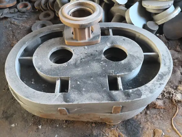
Optimizing sand casting tolerances for precise powertrain assemblies
When manufacturing complex automotive powertrain components such as engine blocks and transmission housings, strict control of sand casting tolerances is critical. In these high-precision applications, even minor dimensional deviations can lead to structural misalignment or premature component failure. Therefore, it is essential to strike a balance between standard sand casting tolerances and post-casting machining requirements to optimize production efficiency and reduce scrap rates. By controlling variables such as mold stability, thermal expansion, and thermal contraction, it is possible to consistently meet strict dimensional targets. This precise control ensures that each casting integrates seamlessly into automated assembly lines, thereby reducing overall manufacturing costs.
Understanding linear and geometric sand casting tolerances in automotive standards
In the automotive industry, sand casting tolerances are specified by international standards such as ISO 8062, which classify deviations in both linear and geometric dimensions. Linear factors relate to the length and thickness of parts, while geometric tolerances control the flatness, parallelism, and cylindricity of castings. To meet these stringent industry standards, the metal shrinkage rate and pattern wear must be accurately calculated during the initial engineering design phase. Therefore, sand casting foundries must strictly monitor mold dimensions and cooling cycles to prevent parts that fall outside the tolerance range from proceeding to the final machining stage.
How CT grades affect machining allowances for engine blocks
The selection of the casting tolerance (CT) grade directly determines the machining allowance required for complex sand-cast engine and drivetrain components. Selecting a stricter CT grade allows engineers to minimize the surface profile of the raw casting, thereby saving valuable aluminum alloy material and reducing cycle times for subsequent CNC machining.
Optimizing these parameters through proper sand casting design ensures proper tool engagement with the workpiece and prevents premature tool wear caused by an excessively hard surface layer on the casting.
ISO 8062 CT Grade | Typical Tolerance Range (mm) | Recommended Machining Allowance (mm) | Primary Automotive Application |
CT 7 | ±0.50 to ±0.90 | 1.5 to 2.0 | Precision Engine Blocks, EV Housings |
CT 8 | ±0.70 to ±1.20 | 2.0 to 3.0 | Standard Gearbox Cases, Oil Pans |
CT 9 | ±1.00 to ±1.50 | 3.0 to 4.5 | Heavy-Duty Structural Brackets |
Minimizing dimensional variation through precision resin mold technology
Our state-of-the-art sand casting facilities utilize precision resin-bonded sand technology, which significantly reduces dimensional tolerances for thin-walled automotive components. Unlike traditional green sand, chemical resin binders form strong and highly stable molds that are resistant to thermal deformation when exposed to molten aluminum. This exceptional mold hardness helps ensure tight tolerances during high-temperature pouring and maintains clear structural contours. To ensure these precise dimensions are not compromised by internal defects, please review our strategies for [sand casting defects elimination in automotive aluminum alloy components].
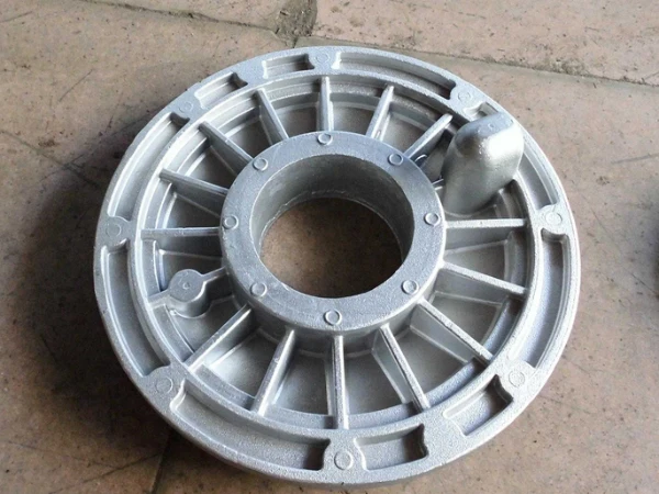
Determining sand casting draft angle and parting line placement
In automotive parts engineering, selecting the precise sand casting draft angle and determining the optimal parting line location are critical steps. These geometric design decisions directly determine whether the core can be smoothly removed from the sand mold without tearing the sand walls. Improper planning of the sand casting draft angle can lead to sand mold damage, surface scaling, and ultimately, dimensional inaccuracies in the castings. By incorporating manufacturing constraints into the initial 3D model, scrap rates can be minimized and mold complexity optimized. Proper implementation of these principles ensures stable and efficient production of molds for complex aluminum automotive components.
Minimum sand casting draft angle requirements for deep-pocket automotive housings
When designing deep-cavity automotive housings, such as oil pans or transmission cases, an accurate sand casting draft angle is critical. Vertical deep walls require a steeper draft angle to ensure that wooden or metal patterns can be smoothly removed from the compacted sand without structural friction. Standard practice specifies that the minimum draft angle on external surfaces should be 1 to 1.5 degrees, while deeper internal cavities may require a draft angle of up to 3 degrees. Insufficient draft angles can cause the sand mold to collapse during model removal, resulting in severe surface defects and costly rework.
How parting line selection impacts draft design and tooling costs
The placement of the parting line serves as the fundamental reference plane for determining the direction of the required sand casting draft angle. Selecting straight, planar parting lines simplifies pattern making, thereby directly reducing the initial CNC mold cost and minimizing future maintenance expenses. However, complex automotive geometries often force foundries to adopt stepped or curved parting lines to protect critical functional surfaces. Improper parting line placement increases the draft angle required for visible dimensions, thereby adding unnecessary mass to the part and violating the vehicle’s strict weight-reduction targets.
Balancing aesthetic surface requirements with functional release angles
A common challenge for automotive engineering teams is striking a balance between aesthetic requirements and the mechanical requirements for the draft angle in sand casting. While the original mounting surface must remain flat, the unmachined outer surface must also have sufficient taper to prevent drag marks during automated molding cycles. This issue can typically be addressed by following a comprehensive aluminum sand casting design guide, which cleverly conceals steep draft angles within internal ribs. This approach satisfies global automakers’ demands for a sleek, minimalist appearance while ensuring the sand casting draft angle required for defect-free, high-volume production.
Critical sand casting minimum wall thickness for structural integrity
Maintaining the correct sand casting minimum wall thickness is a fundamental requirement for ensuring the structural integrity of advanced automotive components. If a part is designed with walls that are too thin, the molten aluminum alloy may cool too quickly, preventing it from fully filling the mold cavity. Conversely, excessively thick walls add unnecessary weight to the vehicle and prolong the cooling cycle, which can lead to internal defects such as shrinkage cavities. Therefore, it is essential to analyze fluid dynamics and solidification behavior during the design phase to optimize material distribution. Striking a balance among these variables is essential for producing components that are both lightweight and high-strength, enabling them to easily withstand extreme mechanical stresses.
Defining the sand casting minimum wall thickness for electric vehicle battery trays
When designing large electric vehicle (EV) battery trays, determining the sand casting minimum wall thickness is a critical engineering step. For automotive-grade aluminum alloys, a nominal wall thickness of 4.0 to 5.0 millimeters is typically required to ensure smooth metal flow across wide horizontal surfaces. If the designed wall thickness falls below this threshold, it may result in insufficient filling; conversely, exceeding this threshold increases the vehicle’s weight, thereby reducing driving range. Supro MFG employs advanced casting simulation technology to verify that every wall thickness design can safely withstand collision impacts while optimizing lightweight structural profiles, ensuring both performance and weight reduction are achieved.
Managing metal fluidity and cooling rates in thin-walled castings
When executing complex sand casting projects involving variable cross-sections or thin-walled sections, controlling the flowability of aluminum alloys is critical. The thermal conductivity of the mold material affects the cooling rate; when molten aluminum flows into thin-walled sections, it rapidly transfers heat to the surrounding sand. To prevent premature solidification of the metal, sand casting foundries strictly control the pouring temperature, typically maintaining it between 700°C and 740°C, and use specialized sand additives to adjust thermal insulation properties. These proactive thermal management measures ensure a consistent grain structure and prevent material degradation in thin-walled sections.
Design practices to prevent premature solidification and cold shuts
Following an industry-proven aluminum sand casting design guide helps ensure smoother transitions in part wall thickness and geometry, thereby effectively preventing premature solidification and cold shuts. When two streams of molten metal converge, if they fail to fuse properly due to low temperature, a cold seam will form, ultimately creating a weak boundary. To eliminate this defect, large fillet radii must be used at wall junctions, and abrupt changes in wall thickness that could disrupt the smooth flow of molten metal must be avoided. By strategically placing risers and optimizing the gating system, molten metal can be delivered in a continuous, pressurized manner, resulting in completely uniform and defect-free automotive castings.
Looking for a reliable China metal foundry?
- We can help you optimize product design and save costs.
- We can help you with high quality high volume cast parts.
- We can deliver on time and get more sales market opportunities.
- You will benefit from Supro MFG metal casting service.
Contact Supro MFG
This paper systematically analyzes the core technical aspects of sand casting in the development of lightweight automotive components. Based on the engineering guidelines outlined in the “Aluminum Sand Casting Design Guide,” it establishes a complete technical closed-loop process—from design specifications to process implementation—focused on three key dimensions: control of casting tolerances at the CT grade level, optimization of draft angles and parting lines, and flow management for sand casting minimum wall thickness. In practice, precision resin mold technology is used to consistently maintain tolerances within the CT7–CT8 range, while the pouring temperature is strictly controlled between 700°C and 740°C to ensure proper filling quality in thin-walled areas. The synergistic optimization of these design guidelines and process parameters is driving the expansion of sand casting from traditional structural components to high-performance applications such as electric vehicle battery trays and integrated subframes, providing vehicle manufacturers with a lightweighting solution that balances cost and precision.
At Supro MFG, we offer IATF 16949-certified aluminum casting solutions to help you accelerate your product development process. Whether you are developing aluminum prototype parts or scaling up for mass production, our team of technical experts is ready to provide end-to-end technical support—from DFM analysis to mass production. Contact us today, and we will review your design and provide a comprehensive manufacturing assessment.