
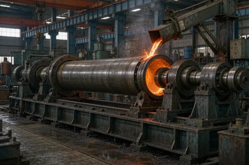
Centrifugal casting is the one casting process where the mold does the pumping. Metal poured into a spinning die is thrown outward against the wall, so you get a dense, low-inclusion cylindrical wall with no riser and no gating system at all. For buyers sourcing cylinder liners, ductile iron pipe, bronze bushings, roll sleeves and ring blanks, that single fact changes both the price and the metallurgy.
It also comes with a trade-off most RFQs miss: the outside diameter is set by the mold, but the inside diameter is set by how much metal you pour. That asymmetry drives tolerances, machining allowance and break-even volume. This guide covers the three centrifugal casting variants, the G-factor math that fixes your spin speed, a real process window for iron, steel, bronze and aluminium, the tolerances you can hold, the ASTM and ISO standards to cite in an RFQ, and a worked break-even against sand casting and bar stock. For industry fundamentals see the Société américaine de la fonderie, and for the wider process map our complete metal casting guide.

What Centrifugal Casting Actually Is
Centrifugal casting is a family of processes in which metal is poured into a mold rotating about an axis, and centrifugal force — measured as a G-factor, usually 40 to 120 times gravity — presses the liquid against the mold wall. Because the force is always directed outward, the denser metal fills the periphery first while slag, dross, gas bubbles and light inclusions are displaced to the bore. In true centrifugal casting that contaminated inner layer is not a defect to chase; it is designed-in material that gets bored out, which is precisely why spun castings show fewer sub-surface inclusions than static castings on the same section.
The absence of risers also means no gating yield loss. A static casting of a hollow cylinder typically pours 60 to 70 % usable metal; a true centrifugal casting of the same part pours 90 to 95 %. That gap, not labour, is what makes centrifugal casting competitive at volume.
The Three Variants — and Which One You Are Buying
“Centrifugal casting” in a quotation can mean three different things. Ask which one before you compare prices, because tooling and tolerances differ by a factor of three.
| Variant | Rotation axis | Part geometry | Core used | Typical parts |
|---|---|---|---|---|
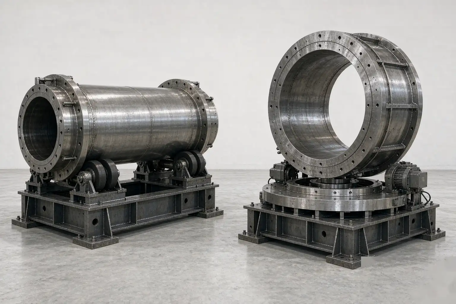
| True centrifugal | Part centreline | Hollow cylinder, one wall | No core — bore is free surface | Pipe, liner, bushing, sleeve, roll |
| Semicentrifugal | Central sprue, part offset | Disc or wheel, plus hub bore | Yes — sand core for bore/holes | Wheel hubs, sheaves, flanges |
| Centrifuging (pressure casting) | Central sprue, cavities around it | Any small part in a radial cavity | Yes, per cavity | Valve bodies, fittings, brackets |
Only the first variant gives you the no-riser, no-core, high-yield economics. If a supplier quotes “centrifugal casting” for a non-axisymmetric part, you are buying the centrifuging variant — useful for thin-wall small parts, but it does not carry the yield advantage. For non-rotational geometry, evaluated properly, sand casting versus investment casting is the more honest comparison, and our sand casting line covers that territory.
The G-Factor Math That Fixes Your Spin Speed
Spin speed is not a preference, it is a calculation. The G-factor is the radial acceleration expressed in multiples of gravity:
G = ω²r / g, where ω = 2πN / 60. Rearranged for a shop-floor set point, N = 9.549 × √(9.81G / r) rpm, with r in metres measured at the bore.
Worked Example: Horizontal Spun Steel Tube
Tube OD 220 mm, bore diameter 180 mm, so r = 0.09 m at the bore and 0.11 m at the mold wall. Targeting G = 60 at the mold wall:
- 9.81 × 60 = 588.6 m/s² of radial acceleration
- 588.6 / 0.11 = 5351, √5351 = 73.1
- N = 9.549 × 73.1 ≈ 700 rpm
At 700 rpm the wall sees roughly 6 g of settling force per kilogram of metal more than gravity alone, which is enough to collapse gas porosity and float inclusions inward. Drop below about G = 40 and the metal no longer sticks reliably to the top of the mold: it rains back down, producing cold laps, cold shuts and a banded, under-dense wall. Push past G = 120 and you start paying for it — circumferential segregation bands in high-carbon and alloy steels, longitudinal cracking on fast-cooled heavy sections, and accelerated mold wear. For the equivalent defect mechanisms in gravity-poured molds, see our notes on défauts courants de moulage et porosity and shrinkage.
Why Vertical Spin Costs You Wall Thickness
In a vertical centrifugal casting the free surface is a paraboloid, not a cylinder. The bore radius therefore shrinks with height, and the relationship is r_bottom² − r_top² = 2gh / ω², where h is the ring height. Take a ring 300 mm OD × 200 mm tall spun at 750 rpm: ω = 78.5 rad/s, ω² = 6168, so 2gh / ω² = (2 × 9.81 × 0.2) / 6168 = 636 mm². If the bore is 240 mm at the bottom (r = 120 mm), the top becomes √(14400 − 636) = 117.3 mm, a bore of 234.6 mm.
Result: wall thickness runs 30 mm at the bottom and 32.7 mm at the top — a 2.7 mm taper on a 200 mm-tall ring, before you even account for mold runout. Every vertical centrifugal casting therefore needs a larger bore allowance than a horizontal one, and it is why pipe and long tubes are always spun horizontally on a machine bed. Vertical machines are reserved for short rings, flanged parts and castings where the axis of the bore is not the axis of the mold.
Process Window for Iron, Steel, Bronze and Aluminium
These are the set points our centrifugal casting cells run. Pour temperature and mold coating matter more than spin speed once the G-factor is inside the band; a cold pour at correct rpm still produces cold laps.
| Parameter | Ductile iron pipe | Carbon / alloy steel tube | Bronze bushing | Aluminium A356 |
|---|---|---|---|---|
| Mold type | Sand-lined steel (De Lavaud) | Water-cooled steel | Steel, coated | Steel, coated |
| Pour temperature | 1,350–1,400 °C | 1,550–1,600 °C | 1,050–1,150 °C | 700–730 °C |
| Mold temperature | Ambient lining, 80–150 °C shell | 150–300 °C | 150–250 °C | 200–350 °C |
| G-factor | 40–80 | 60–120 | 60–100 | 50–90 |
| Mold coating | Sand lining, no wash | Zircon or alumina wash | Graphite wash | Zircon wash |
| Cooling | Air, slow (avoids carbides) | Water spray, then in-line | Air | Air, forced |
| Post-process | Annealed to ferritic matrix | Normalise or quench-temper | Stress relief | T6 solution + age |
Defects That Only Show Up in Spun Castings
- Raining and cold laps. Pour rate too low or G-factor too low for the mold diameter. Metal leaves the top of the shell and falls back through the stream. Cure: raise rpm first, then raise pour rate.
- Banding. Circumferential stripes from machine vibration or a fluctuating drive. Visible on radiography as a periodic density change. Cure: balance the mold, stiffen the drive, hold constant rpm through solidification.
- Tin sweat (inverse segregation). In tin- and lead-bearing bronzes, the low-melting phase is squeezed outward and beads on the outer surface. Cure: lower pour temperature, tighter chemistry control on Sn and Pb.
- Longitudinal cracking. High G-factor plus rapid cooling on a heavy wall locks in hoop stress. Cure: reduce rpm after fill, slow the cooling, normalize before machining.
- Bore-side inclusion band. Not a defect — it is the trapped dross layer. It only becomes a defect if the machining allowance is too small to remove it. Budget 3 mm minimum on the bore.
Mold runout and rotation also set the wall-thickness variation you will see after boring. Verify it with the same tooling used for static castings: see our breakdown of casting inspection methods for radiography, ultrasonic and penetrant practice on hollow sections.
Tolerances: Why the Bore Is Always Loose
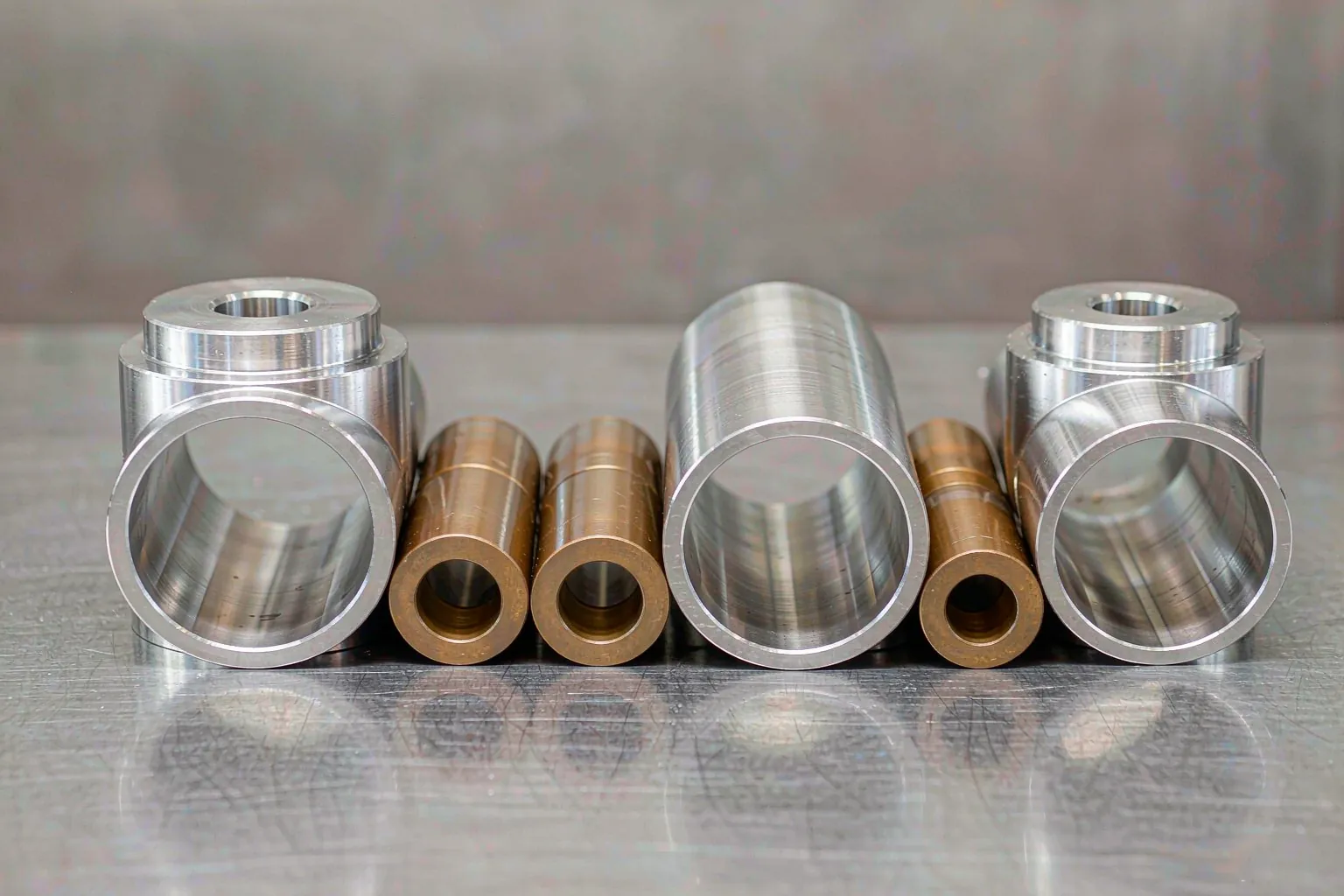
In centrifugal casting the wall thickness is a consequence of mass balance, not of the mold cavity. That is the single most important thing to know when you write a drawing. A horizontal centrifugal casting holds a normal casting-grade outside diameter — comparable to a good sand casting CT grade — but the bore inherits the tolerance of the ladle.
Worked case: a steel tube OD 220 mm × L 400 mm with a nominal 180 mm bore. The bore area is π/4 × 180² = 25,447 mm². If weighing and pouring accuracy is ±1.0 % of the target mass — a realistic figure for a 40 kg pour on a calibrated scale — the volume varies ±1 %, so the bore radius varies ±0.5 %, or about ±0.9 mm from mass variation alone. Add mold runout and thermal distortion and the realistic as-cast figure is ±1.5 mm.
| Feature | Set by | Typical as-cast | Machining allowance |
|---|---|---|---|
| Outside diameter | Mold bore + shrinkage + coating | ±1.0 mm on Ø220 | 1.5–2 mm |
| Bore | Poured metal mass | ±1.5 mm (up to ±2 mm on long tubes) | 3 mm minimum, 4 mm preferred |
| Length | Mold end stop | +2 / −1 mm | 3–5 mm per end |
| Concentricity (TIR) | Mold runout + spin balance | 0.5–1.0 mm | Absorbed by bore allowance |
| Ovality | Mold roundness, coating build-up | 0.4–0.8 mm | Absorbed by bore allowance |
Practical rule: specify as-cast only the outside diameter, length and any unmachined flange faces. Put the bore, concentricity and surface finish as machined dimensions after boring. If you need a bore tolerance tighter than ±0.5 mm, you are buying a machined feature, and that is a normal and cheap addition when the machining allowance is already there. For ISO 8062 grade selection and how to convert grade to a millimetre value on your drawing, see our casting tolerances reference.
Materials and the Standards Your RFQ Should Cite
Centrifugal casting covers more of the metals spectrum than most buyers expect — from spun ductile iron water main to austenitic reformer tube to tin bronze bearing stock. Cite the standard, not just the alloy name, so the mechanical property requirements travel with the purchase order.
| Material family | Standard to specify | Typical spun part |
|---|---|---|
| Ductile iron pipe | ISO 2531 / EN 545 / AWWA C151 | Water and sewer mains, 80–1,000 mm DN |
| Carbon steel pipe, high temperature | ASTM A660 | Steam and process piping |
| Ferritic alloy steel pipe | ASTM A426 | Refinery and power station pipe |
| Austenitic steel pipe | ASTM A451 | High-temperature and corrosion service |
| Copper-base alloys | ASTM B271 | Bearings, bushings, worm gear blanks |
| Fonte grise et fonte ductile | ASTM A48 / ASTM A536 | Cylinder liners, ring blanks, pulleys |
| Carbon and low-alloy steel | Customer spec with grade and property class | Roll sleeves, mill rolls, hydraulic tube |
Standard scopes are published by ASTM International; always quote the revision year on the drawing so the tensile, elongation and hydrostatic test requirements travel with the order. Property differences inside a family are worth checking before you assume equivalence. The distinction between cast iron and cast steel, and between gray iron and ductile iron, is usually the deciding cost and impact-toughness factor on a liner or roll program. Our iron casting, pièce moulée en acier, pièce moulée en acier inoxydable et copper and bronze casting cells all quote against these standards; when the grade needs through-hardening or a specific matrix, that is sequenced through traitement thermique or our in-house heat treatment line.
The Cost Case: Material Yield, Not Labour
Centrifugal casting is more expensive on tooling and cheaper on metal. The entire break-even argument lives in that trade. Take the same steel tube used earlier — OD 220 mm, bore 180 mm, length 400 mm, density 7.85 g/cm³.
- Finished casting mass: π/4 × (220² − 180²) × 400 = 5.03 × 10⁶ mm³ = 5,027 cm³ → 39.5 kg
- Centrifugal at 93 % yield: 42.5 kg poured
- Sand cast with a core at 70 % yield: 56.4 kg poured — 13.9 kg of extra melt every cycle
- Metal price at $1.60/kg melted and poured → the riser and gating cost $22.24 per part, plus knockout and cut-off labour
- Tooling delta: a spun steel mold with drive ring and cooling jacket at $5,500 versus a sand pattern and core box at $900 → $4,600
- Break-even: $4,600 ÷ $22.24 ≈ 207 parts
Above roughly 200 pieces a year, the spun route wins on metal alone, before counting the density and inclusion benefits. Below it, a static casting or a cut length of tube is cheaper.
Against Machining From Bar
The comparison that changes the most minds is bar stock. A solid 220 mm bar 400 mm long is π/4 × 220² × 400 = 15.2 × 10⁶ mm³ = 119.4 kg of purchased metal to deliver a 39.5 kg part — 79.9 kg of chips, a buy-to-fly ratio of 3.0:1. At $2.40/kg for bar against $1.60/kg for poured metal, the raw material bill is $286 versus $68. That is $218 saved per part before you account for the machining hours needed to remove 80 kg of steel.
| Route | Metal purchased | Material cost / part | Metal removed | Best for |
|---|---|---|---|---|
| Centrifugal casting | 42.5 kg | ≈ $68 | ≈ 8 kg (bore plus OD cleanup) | 200+ pcs/yr, hollow axisymmetric |
| Sand cast, cored | 56.4 kg | ≈ $90 | ≈ 8 kg plus gate removal | Any geometry, low volume |
| Machined from bar | 119.4 kg | ≈ $286 | ≈ 80 kg | 1–20 pcs, tight ID |
Machined-from-bar still wins below roughly 20 pieces, because there is no tooling and no lead time. Between 20 and 200 pieces the decision usually comes down to whether you can wait for a mold. Our répartition des coûts de moulage covers the volume bands in more detail, and for the low-volume end we quote metal prototype castings so a program is not blocked while tooling is cut.
When Centrifugal Casting Wins — and When It Does Not
| Decision factor | Centrifugal casting wins | Choose another process |
|---|---|---|
| Geometry | Hollow, single axis of symmetry, length-to-diameter 1 to 20 | Ports, ribs, bosses, non-axisymmetric flanges |
| Tooling | Simple steel mold or tube, no pattern equipment | Where a reusable pattern pays back faster — see conception de moules et de modèles |
| Metal yield | 90–95 %, no riser or gating | Static routes at 60–70 % — see riser and feeding design |
| Soundness | Dense, fine grain near the OD; inclusions driven to the bore | Wall-thickness-critical parts where you cannot bore 3 mm |
| Wall thickness | 8–50 mm comfortable across iron and steel | Below 6 mm in steel, or high-aspect thin rings |
| Volume | 200+ pcs/yr for the same part number | Single prototypes and spares — 3D printed patterns beat a mold on lead time |
| Service conditions | Wear, pressure and high temperature — liners, rolls, mains | Where forged hoop properties are mandatory — see casting versus forging |
Two adjacent processes come up in almost every comparison. Permanent mold casting suits non-hollow aluminium geometry at 1,000 to 20,000 pieces a year; moulage par mousse perdue suits complex, cored geometry where the part is not rotationally symmetric. Neither delivers the centrifugal casting yield advantage, and neither can match its combination of dense periphery and cheap tooling. For aluminium-specific selection, the A356 versus A380 comparison covers the alloy side.
FAQ
What parts are made by centrifugal casting?
Cylinder liners, ductile iron water and sewer mains, bronze and copper-alloy bearings and bushings, roll sleeves, mill rolls, ring and flange blanks, brake drums and hydraulic cylinder tubes. The common thread is a hollow body with one axis of symmetry and a wall you would otherwise have to bore out of solid stock.
Why does centrifugal casting not need a riser?
Because centrifugal force feeds the wall continuously from the whole inner surface, not through a single gravity path. As the casting contracts, liquid metal is pushed outward by the same force that shaped it, so there is no shrinkage cavity to compensate with a feeder. That is why spun castings reach 90 to 95 % yield against 60 to 70 % for static molds. Heat treatment may still be required to relieve the stresses that come with rapid cooling.
How long can a centrifugal casting be?
Spun ductile iron pipe production runs to 6 m in a single pour; steel tube and roll sleeves commonly run 1 to 4 m. The limit is machine bed stiffness and the fact that the free end of a long mold deflects, which changes the G-factor along the length and shows up as wall-thickness variation. Longer than 6 m is normally welded or joined rather than spun.
Can centrifugal casting make a part that is not round?
Only through the centrifuging variant, where multiple shaped cavities sit around a central sprue in a rotating flask. True centrifugal casting cannot, because the bore is a free liquid surface. If your part has ports, ribs or flat flanges, ask a foundry for a process comparison rather than assuming a spun quote applies; our casting alloy selection guide and process pages cover the static alternatives.
What bore tolerance can a centrifugal casting hold as cast?
Expect ±1.5 mm on a typical tube and up to ±2 mm on a long or heavy one, because the bore is set by the mass of metal poured. A ±1.0 % weighing error on a 180 mm bore moves it about ±0.9 mm by itself. Specify 3 mm of bore allowance, machine to your drawing tolerance, and the as-cast variation disappears into the cut.
Is centrifugal casting cheaper than sand casting?
Per part, above roughly 200 pieces a year for the same part number, yes — on a 39.5 kg steel tube the spun route saves about $22 in metal per piece against a cored sand casting, which pays back roughly $4,600 of extra tooling after 207 parts. Only that part family counts. If your program is a handful of prototypes, sand or bar stock will be cheaper on total cost of ownership, and our CNC machining capacity covers the finish-machining side either way.
*Data referenced from AFS industry publications, ASTM A660 / A426 / A451 / B271 standard scopes and Supro MFG shop-floor records.
 English
 Français
 Deutsch
 Italiano
 日本語
日本語 한국어
한국어 Polski
 Português de Angola
 Русский
 Español de Argentina