
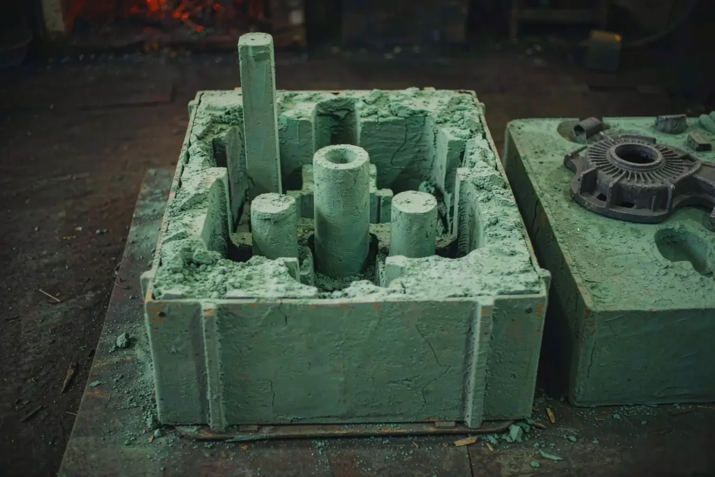
Most shrinkage porosity is not a pouring problem. It is a rigging problem, and it is already baked into the drawing weeks before the first heat. Casting riser design decides which metal stays liquid longest, and it remains the cheapest lever you have on both soundness and yield.
This guide covers the part of foundry engineering buyers rarely see but always pay for: how a riser is sized, where it goes, what it costs to remove, and how to read the rigging drawing a supplier sends back. Every rule here is the one we actually apply on the floor, cross-checked against published data from the American Foundry Society (AFS) and the Steel Founders’ Society of America (SFSA). For the wider process context, start with our metal casting guide. If you take one sentence away from this page: sound casting riser design is a thermal-gradient problem, not a metal-volume problem.

What Casting Riser Design Actually Controls
A riser is a reservoir of liquid metal attached to the casting so that the shrinkage the part undergoes on freezing is fed from outside instead of forming a void inside. That is the whole job. Everything else — shape, sleeve, neck, location — is a way of making that reservoir freeze after the section it is feeding, which is why casting riser design is settled on the drawing board, long before any tooling is cut.
When it fails, the result is the family of defects covered in sand casting porosity and shrinkage: centerline sponginess, a cavity under a heavy boss, or a leak path that only shows up at pressure test. Most of those are not melt-quality issues. They are geometry and thermal-gradient issues that a second look at casting riser design would have caught.
The three shrinkages are not the same problem
Metal contracts three times: as liquid cools from pouring temperature to the liquidus, as it changes phase from liquid to solid, and as the solid cools to room temperature. Only the first two are fed by a riser. The third is handled by the patternmaker’s shrink rule and belongs to mold and pattern design, not to feeding. Keep that line straight and casting riser design stops looking mysterious.
| Alloy | Solidification shrinkage | What it means for feeding |
|---|---|---|
| Gray iron, CE ≈ 3.9–4.1 | ≈ 1.9 % | Graphite precipitation expands and offsets much of it; many uniform sections run with no riser at all |
| Ductile iron, CE ≈ 4.3–4.5 | ≈ 4.0–5.0 % | Needs real feeding; mold rigidity drives the outcome as much as riser volume does |
| Carbon steel, 0.35 % C | ≈ 5.5 % | Heaviest feeding demand; risers are large and yield is the economic constraint |
| Al–Si, A356 / Al–12 % Si | ≈ 3.8 % | Eutectic freezes over a narrow range; small, well-placed risers plus chills usually suffice |
| Al–4.5 % Cu | ≈ 6.3 % | Wide freezing range; dispersed microporosity rather than one clean cavity |
| Tin bronze and copper alloys | ≈ 4.0–5.0 % | Wide freezing range plus high thermal conductivity; short feeding distance, aggressive chilling |
Read that table as a demand signal, not a sizing formula. The same percentage behaves very differently in a 12 mm rib and in a 120 mm hub, which is why casting riser design is always sized from geometry rather than from alloy alone. It is also why alloy selection and feeding should be decided in the same meeting, not sequentially.
Sizing a Riser with Chvorinov’s Rule
The sizing half of casting riser design rests on one relationship, Chvorinov’s rule: solidification time is proportional to the square of the modulus, where modulus is volume divided by cooling surface area.
M = V / SA → t = k · M²
The constant k absorbs mold material, superheat and alloy properties, and honest foundries calibrate it per alloy–mold pair rather than lifting it out of a handbook. The useful part is that you rarely need k at all. Because the exponent is 2, the ratio of freezing times is just the square of the modulus ratio — so you can size a riser without knowing a single absolute time.
The standard practice behind most casting riser design is to give the riser a modulus 1.2 × the modulus of the section it feeds. That gives:
t_riser / t_casting = 1.2² = 1.44
In plain terms: the riser stays liquid about 44 % longer than the part. That margin is what covers superheat variation, mold density drift and the fact that nobody pours at exactly the specified temperature every time.
Worked example: a cast steel hub
Take a solid steel hub, 100 mm diameter × 150 mm tall. Work in centimetres so the modulus comes out in cm:
- Volume. V = π r² h = π × 5² × 15 = 1178 cm³
- Cooling area. SA = 2πr² + 2πrh = 157 + 471 = 628 cm²
- Modulus. M = 1178 / 628 = 1.875 cm
- Required riser modulus. 1.2 × 1.875 = 2.25 cm
Now pick a shape. For an open-top cylindrical riser with height equal to diameter, the exposed surfaces are the side wall and the base (the open top loses heat too, but slowly, and is normally ignored), giving M = D / 5. So D = 5 × 2.25 = 112 mm, and H = 112 mm.
Riser volume = π/4 × 11.2² × 11.2 ≈ 1104 cm³, against a casting volume of 1178 cm³. At steel’s 7.85 g/cm³ that is roughly 8.7 kg of riser for a 9.2 kg casting, and a casting yield of about 52 %.
That ratio shocks buyers the first time they see it. It should not. A properly fed steel casting routinely gives up half its poured weight to the rigging, and this is exactly the line item broken down in our casting cost breakdown. The engineering question is not “why is the riser so big” but “what do I gain by making it smaller”.
Taller is not more efficient
Stretching the same riser to H = 1.5 D raises its modulus for a given diameter, so the diameter can shrink to 105 mm — but the volume rises to about 1346 cm³ and yield drops to roughly 47 %. You spend about 22 % more metal to buy metallostatic head and a longer feeding distance. That trade is worth it when the riser has to reach a distant heavy section; it is pure waste when it does not.
This is the point where casting riser design stops being a formula and becomes a judgment call. The formula tells you the modulus. Only the geometry tells you whether the feed path stays open long enough to use it.
Riser Types and What Each One Buys You
Once the modulus is fixed, the sleeve is the cheapest way to hit it with less metal — the single most under-used tool in everyday casting riser design. An insulating or exothermic sleeve slows heat loss from the riser surface, so a physically smaller riser behaves like a bigger one.
| Riser type | Typical use | Effective modulus gain | Trade-off |
|---|---|---|---|
| Open top riser | Steel and iron sand castings, sitting on the heaviest top face | 1.0 × (baseline) | Simple and reliable; lowest metal efficiency |
| Blind side riser | When the top face is machined off or unreachable | ≈ 0.85–0.9 × | Loses the open-top benefit; needs a breaker or atmospheric core to feed against vacuum |
| Insulating sleeve | Medium to large steel and iron sections | ≈ 1.3–1.5 × | Yield typically improves 10–20 points; sleeve cost and placement labour |
| Exothermic sleeve | Heavy steel sections, low superheat pours | ≈ 1.5–1.7 × | Highest yield gain, 15–25 points; highest unit cost and fume handling |
| Pressure or riserless design | High-carbon-equivalent ductile iron in rigid molds | n/a — uses graphite expansion and mold strength | Best possible yield, but a narrow process window; one loose flask and the part is scrap |
If a supplier proposes bare sand risers for a heavy steel casting without explaining why sleeves were rejected, ask for the yield number. On a 500-piece annual run, ten points of yield is a real line in the budget — and it usually justifies the sleeve in the first hundred parts.
Placement: Feeding Distance and Directional Solidification
Placement is where casting riser design most often fails. A riser that is big enough but too far away still produces scrap. Liquid metal can only travel through a mushy zone while a continuous feed path exists, and that path closes as the section between riser and hot spot freezes. The practical limit is expressed as a multiple of section thickness T.
| Condition | Feeding distance in steel plates | Why |
|---|---|---|
| Single riser, uniform plate, no chill | ≈ 4.5 – 6 T | Baseline gradient a sand mold can sustain |
| Riser near a free edge or corner | ≈ + 2 T (end effect) | Extra cooling surface shortens local freezing time and steepens the gradient |
| External chills applied between riser and hot spot | Up to ≈ + 50 % | Chill creates an artificial gradient that keeps the feed path open further out |
| Deliberate taper toward the riser | Extends with taper, commonly ≈ 5 % per 100 mm | Progressive thickening is the strongest directional-solidification tool available |
Aluminum and copper alloys feed over shorter distances than steel, so the multipliers above are a steel rule of thumb, not a universal constant. Treat them as a screening check: if a heavy boss sits more than six times its own thickness away from the nearest riser, casting riser design has a gap and the drawing should go back for review.
Chills, padding, and isolated hot spots
Every isolated heavy section is a small casting with its own feeding requirement. You have three moves, in order of preference:
- Remove it. Core out the boss or thin the rib. The cheapest riser is the one you never needed. Uniform section thickness is also the single biggest driver of the dimensional results discussed in our casting tolerances guide.
- Chill it. An external chill pulls local freezing time down so the section solidifies before the feed path closes. Cheap, and reversible between trials.
- Feed it. Add a riser or local padding. Effective, but it adds metal, removal labour and a weld-inspection point.
On aluminum housings we chill far more often than we riser, because the aluminum casting freezing range is narrow enough that a well-placed chill solves in one trial what a riser solves in three.

Neck Design and the Cost of Getting the Riser Off
A riser has to be removed, and that removal is a machined surface you are going to inspect. The neck is where casting riser design meets the finishing budget.
The neck must freeze after the section it feeds but before the riser body, so what is left attached to the casting is small. If the neck is too large, the riser cannot be broken or cut off cleanly and you are grinding a large pad; if it is too small, it freezes early and the riser stops feeding while the casting is still shrinking.
Two common solutions:
- Knock-off (Washburn) cores. A refractory core reduces the metal contact area to roughly a third of the riser base, so a riser that would need torch cutting can be knocked off with a hammer. Standard on ductile iron and increasingly on small steel work.
- Tapered or knife-edge necks. Used where the riser sits on a surface that will be machined anyway, keeping the grind local.
Good casting riser design treats removal as part of the thermal design, not an afterthought. On our floor, torch cutting and grinding a 110 mm steel riser runs 10–25 minutes of finishing labour per piece, and every cut riser leaves a spot that has to be checked. That is why we push neck design back to the drawing stage rather than letting it be decided on the shakeout floor. The same logic applies to the CNC machining allowance around riser pads: put the riser on a non-critical face wherever the geometry allows.
Casting Riser Design Checklist Before You Release a Drawing
Run this before the rigging drawing goes to tooling. It takes twenty minutes, and it is usually the difference between a first-article approval and three rounds of scrap. Print it next to the drawing and casting riser design becomes a review step instead of a rescue operation.
- Section thickness map. Mark every region thicker than its neighbours by more than 2 : 1. Each one is a feeding requirement.
- Modulus of the heaviest section. Compute M = V/SA and set riser modulus at 1.2 ×.
- Feeding distance check. Every heavy section must sit within the alloy’s feeding distance of a riser, or be chilled.
- Directional path. Thickness should increase toward the riser. No isolated thick island with thin metal on both sides.
- Neck and removal plan. Decide now how the riser comes off, and where the grind mark lands.
- Yield estimate. Casting weight divided by poured weight. For steel, expect 45–55 %; if the number comes out at 70 %, the risers are probably undersized.
- Simulation cross-check. Modulus maps and a Niyama-type criterion plot, not just a colour picture. The threshold is alloy-specific — ask which value they use and what it was calibrated against.
That last item is worth insisting on. A colour image proves nothing; a criterion plot with the threshold stated is auditable, and it is the same evidence you will want available when the first production lot goes to casting inspection.
How to Read a Supplier’s Rigging Drawing
You do not need to be a foundry engineer to judge casting riser design on someone else’s drawing. Ask five questions and listen to how confidently they are answered:
- What is the riser-to-casting modulus ratio? Anything below 1.2 deserves a written justification.
- What is the projected yield? If they cannot say, they have not costed the job properly.
- How far does each riser feed, and what is the section thickness at the far end? This is where most shrinkage claims originate.
- Where do the riser pads land relative to machined faces and sealing surfaces? A pad on a gasket face is a future leak claim.
- What changes if we add a taper or a core here? A supplier who has already priced the design alternative understands the part.
The same thinking scales across processes, and casting riser design is only one of them. Die casting has no sand risers at all, which is one reason the yield story differs so sharply between die casting and sand casting. Investment casting feeds through the cluster, not through individual risers, so the equivalent question is about gate location and cluster thermal mass — see our investment casting process notes. And when a part is a poor casting candidate regardless of rigging, the honest answer may be a different process entirely, which is the comparison we run in casting vs forging.
Rigging decisions also interact with downstream heat treatment. A casting that fed well but has a riser pad left in place will respond unevenly in the furnace, and the residual stress pattern follows the thermal mass — worth reading together with heat treatment for castings and our heat treatment services.
Finally, remember that material choice sets the feeding demand in the first place. The jump from gray iron to ductile iron, or from A356 to A380 in our aluminum casting alloys comparison, changes both the riser size and the risk of dispersed microporosity. For iron work specifically, the feeding window is tied to carbon equivalent, covered in more depth on our iron casting page.
FAQ
How large should a riser be?
In casting riser design the answer is always relative to the part: large enough that its modulus is 1.2 × the modulus of the heaviest section it feeds, which makes it freeze roughly 44 % later. On steel that usually means the riser weighs close to the casting; on aluminum, chills often do more work than riser volume.
Can a casting be made without any riser?
Yes, and it is common. Gray iron often feeds itself because graphite expansion offsets shrinkage. High-carbon-equivalent ductile iron in a rigid mold can run riserless, though the window is narrow. Thin-wall aluminum and die cast parts rely on chills, pressure and rapid solidification instead.
Where should the riser sit on the part?
Casting riser design puts the riser on or adjacent to the heaviest section, above it where possible so gravity helps, and on a face that is not a sealing or cosmetic surface. Sections further than roughly six times their thickness away need a second riser or a chill.
Why was the riser full of metal but the casting still shrank?
Because a full riser only proves metal was present, not that a feed path stayed open. If the neck froze early, or the section between riser and hot spot solidified first, the riser is simply a lump of steel sitting on a sealed casting. That is a placement and gradient failure, not a volume failure.
Does riser design change what I machine?
It changes where the machined surface starts. Riser pads, neck stubs and the heat-affected zone under a torch cut all have to be removed, and on steel that pad can be harder than the surrounding metal. Agree the pad location before tooling so the sand casting drawing and the machining drawing agree.
Is simulation worth it for a single prototype?
Usually yes for steel and large iron, usually no for small aluminum. The cost of one simulation run is far below one scrapped large casting plus a tooling modification. For quick prototype work, a casting mold and pattern iteration is often the faster route, and 3D printed prototypes let you validate geometry before the rigging is frozen.
*Data referenced from AFS and SFSA publications, Chvorinov modulus practice, and Supro MFG shop-floor records.
 English
 Français
 Deutsch
 Italiano
 日本語
日本語 한국어
한국어 Polski
 Português de Angola
 Русский
 Español de Argentina