
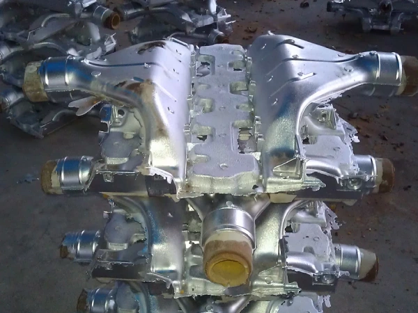
The core challenge of sand casting in the process of automotive weight reduction lies in striking a balance between thin-walled designs and reliable mold filling. While reducing wall thickness directly reduces weight, it significantly increases the flow resistance of molten aluminum within the mold cavity, leading to casting defects such as cold shuts and underfill. This article utilizes the systematic framework of the aluminum sand casting design guide to outline actionable design guidelines for automotive aluminum structures, focusing on key dimensions such as setting thresholds for minimum wall thickness in sand casting, controlling the limits of molten aluminum flowability, ensuring sand casting core stability, and optimizing rib layout and wall thickness transitions. Based on actual process windows, we will analyze, point by point, how to ensure the structural integrity of castings and process yield while meeting weight reduction targets.
Establish sand casting minimum wall thickness standards for automotive aluminum
In the field of automotive lightweight structural engineering, establishing clear minimum wall thickness limits for sand casting is critical. When designing aluminum chassis housings or engine blocks, specifying unachievable thin-wall dimensions will severely restrict metal flow, leading to premature solidification before the mold cavity is fully filled. Therefore, a balance must be struck between structural weight reduction goals and the thermodynamic realities of mold filling to avoid severe cold shut defects. Setting precise wall thickness thresholds based on part dimensions ensures consistent liquid metal coverage during high-volume production. Ultimately, adhering to standardized wall thickness guidelines guarantees structural integrity while optimizing the overall weight of the casting.
Determining foundational wall thickness thresholds based on casting size
The sand casting minimum wall thickness limits are directly related to the total surface area and geometric shape of automotive components. Small structural brackets less than 300 millimeters in length can easily achieve nominal wall thicknesses of 3.0 to 3.5 millimeters. However, large powertrain housings require a minimum wall thickness of 4.5 to 5.0 millimeters to prevent obstructions to molten metal flow.
Following a comprehensive aluminum sand casting design guide can help prevent localized solidification during the pouring stage. Adhering to these calibrated dimensional limits ensures optimal mechanical properties without adding unnecessary weight.
Fluid dynamics of molten aluminum in narrow mold channels
In aluminum sand casting, due to aluminum’s high thermal conductivity, molten aluminum rapidly loses heat as it enters narrow mold cavities. When molten metal flows through narrow walls less than 3.0 millimeters thick, viscous resistance increases sharply, causing the fluid velocity front to drop below the critical filling velocity. This fluid stagnation increases surface tension and causes cold shuts to form on the casting surface. An optimized aluminum sand casting design guide can be used to calculate appropriate gating pressure and runner dimensions. Maintaining a controlled filling velocity effectively prevents premature solidification in thin-walled cavities.
Understand liquid fluidity limits in aluminum sand casting design guide
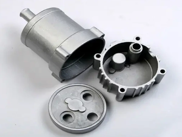
In the aluminum sand casting design guide, understanding the flow limits of molten metal is critical to preventing premature solidification during the filling process. When casting complex automotive components, molten aluminum must flow through narrow channels to prevent heat loss that could cause it to lose its liquid state. Metallurgical variables such as pouring temperature, silicon content in the alloy, and heat absorption by the mold directly determine the molten metal’s ability to flow over distance. If the leading edge of the molten metal cools too rapidly, severe filling defects will form in thin-walled sections. By applying proven aluminum sand casting parameters, metal flow behavior can be accurately predicted to ensure complete mold filling without compromising the integrity of the casting.
Metallurgical fluid temperature and fluidity factors during mold filling
According to the aluminum sand casting design guide, precisely controlling the superheat temperature between 710°C and 740°C can directly improve metal fluidity in thin-walled sections. In commonly used alloys such as A356, a higher silicon content significantly lowers the liquidus temperature, allowing the molten alloy to flow more smoothly through narrow mold channels. However, excessively high pouring temperatures can exacerbate oxide formation and gas absorption, thereby causing secondary quality issues. Adhering to optimized casting procedures ensures a balance between heat input, flow rate, and solidification rate, thereby guaranteeing smooth metal distribution within the complex geometries of parts.
Preventing cold shuts and misruns in thin structural walls
Maintaining an appropriate minimum wall thickness in sand casting prevents cold seams and runner defects caused by premature solidification as the metal front advances. When two streams of cooled molten aluminum intersect but fail to fully merge, localized structural discontinuities can weaken the part’s strength under fatigue loads. Furthermore, rapid heat loss in thin-walled areas can disrupt the flow path of the molten metal, leading to severe shrinkage cavities and porosity. To achieve optimal mechanical properties after a defect-free casting, learn about our approach to [Porosität und Schwindungskontrolle beim Sandguss von Aluminium-Automobilkomponenten].
Integrate high-precision sand casting core systems for hollow structures
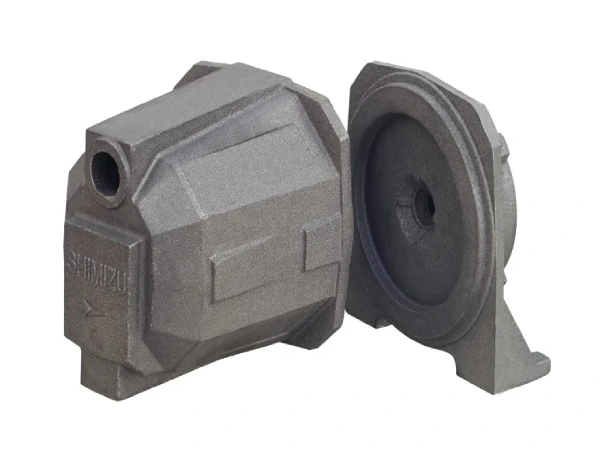
Sand casting core box systems provide the necessary geometric support for manufacturing complex hollow passages in modern automotive aluminum parts. When casting complex engine manifolds or suspension control arms, internal core boxes are subjected to immense thermal and mechanical stresses generated by the surrounding molten metal during the filling process. If the core box support design is inadequate, buoyancy can cause internal displacement, resulting in wall thickness variations. The use of rigid core box models and high-strength resin binder systems maintains precise positioning under turbulent filling conditions, ensuring accurate internal channel dimensions for high-performance, lightweight parts while preserving their structural integrity and consistency.
Structural design limits for cantilevered and supported sand cores
Sand casting cores must maintain high flexural strength to withstand deflection caused by turbulent molten metal flow during pouring. Cantilever cores are particularly susceptible to thermal deflection; therefore, the length-to-diameter ratio must be kept below 3:1 to prevent positional displacement. Cores supported at both ends can withstand greater fluid forces, allowing for longer internal passages in lightweight automotive components. Following the aluminum sand casting design guide can help engineers determine the appropriate core support length, prevent the core from floating, and ensure uniform internal wall thickness.
Balancing core print stability with internal liquid metal pressure
In aluminum sand casting, during the mold cavity filling stage, molten aluminum exerts considerable upward buoyancy on the internal sand cores. The core recesses must have sufficient bearing surface area to evenly distribute these hydraulic loads to the surrounding mold walls, thereby preventing the cores from sinking or shifting out of position. If the mating surfaces of the core recesses are too narrow, thermal pressure can cause deformation at the mold joints, thereby affecting the minimum wall thickness of the sand-cast part’s shell. Designing wide, tapered core recesses ensures stable positioning accuracy and maintains rigid structural boundaries throughout the solidification process.

Manage section thickness transitions in aluminum sand casting designs
In aluminum sand casting, proper control of wall thickness transitions is critical for preventing thermal stress concentration and localized cooling defects. When there is an abrupt step change between a thick mounting boss and a thin-walled structure, uneven cooling rates can lead to thermal tearing and localized internal porosity. A tapered design with a gradual transition allows heat to dissipate evenly toward the outer pouring zone, thereby stabilizing the solidification front. In addition, mold designers must ensure consistent draft angles across these stepped cross-sections to prevent unexpected metal accumulation. Mastering these cross-sectional transitions during the casting process ensures that high-stress automotive structural components achieve uniform grain density and exceptional mechanical durability.
Applying progressive wall tapers to minimize stress concentrations
According to the standard aluminum sand casting design guide, a gradual wall thickness design can prevent severe stress peaks at cross-sectional junctions. When a thin wall is directly connected to a thick-walled structural feature, uneven solidification occurs at the sharp junction, creating localized hot spots that can lead to tearing. A tapered wall thickness design with a ratio of 1:3 or 1:4 ensures a smooth transition of the thermal gradient from thin walls to thick walls during cooling. This gradual geometric reduction eliminates sharp internal corners, ensuring that the part maintains its nominal sand casting minimum wall thickness while preventing the formation of destructive structural stress points.
Aligning draft angles with parting lines across thickness steps
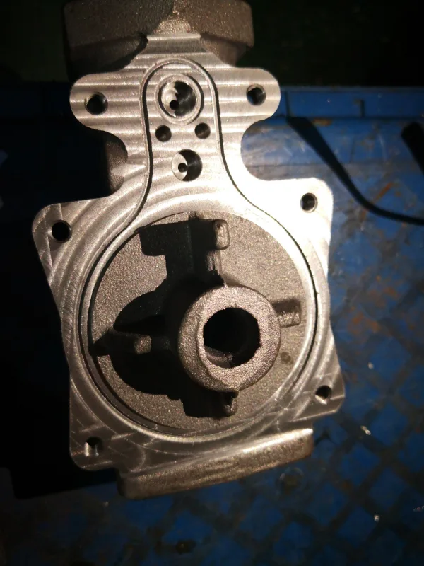
In aluminum sand casting, if the parting line is improperly positioned, the inclusion of a draft angle at the transition of stepped walls may inadvertently result in excessive local wall thickness. When the taper of the pattern is superimposed on a thick-walled step, this composite geometry increases thermal mass, thereby hindering smooth pattern removal and slowing the cooling rate. Strategically positioning the parting line at the thickest step in the geometry addresses this accumulation issue while protecting the sand casting core prints within the adjacent hollow cavities. To achieve optimal mechanical properties in defect-free castings, learn about our approach to [Optimierung von Formschrägen und Trennfugen im Sandguss für Automobilteile].
Optimize structural rigidity using ribs in sand casting components
Incorporating structural ribs into aluminum sand casting designs can maximize component stiffness without significantly increasing the part’s weight. Compared to increasing the nominal wall thickness of the entire housing, properly arranged ribs can both distribute dynamic mechanical loads and maintain flow paths for molten metal. However, an improper rib-to-wall ratio can lead to an increase in local thermal mass, creating hot spots that can cause sink marks and internal shrinkage cracks. Adhering to strict Sandguss design rules ensures that the rib-to-wall ratio strikes a balance between mechanical performance and heat dissipation. A properly designed rib network structure enables the production of automotive components that are lightweight while maintaining high torsional stiffness and structural integrity.
Proportioning rib thickness to primary wall dimensions
According to the current aluminum sand casting design guide, the root thickness of ribs should be set at 0.6–0.8 times the main wall thickness. If the thickness at the base of the rib is equal to or greater than the main wall thickness, a distinct thermal hotspot will form at the junction; this area will solidify last, thereby causing internal shrinkage. Maintaining this ratio ensures that the ribs cool before the shell does, thereby preventing sink marks and maintaining the sand casting minimum wall thickness . This balanced ratio allows the automotive shell to achieve maximum structural rigidity without compromising the density of the internal material.
Designing optimal junction radii to eliminate shrinkage cracks
Optimizing the fillet radii at joints in aluminum sand castings can prevent severe stress concentrations and thermal tearing at the junctions between ribs and the main structural walls. Sharp internal corners impede the flow of molten aluminum, leading to sudden increases in local stress and causing cooling cracks during thermal contraction. Using fillets equivalent to 0.5 to 1.0 times the wall thickness helps facilitate smooth heat transfer from the junction, thereby protecting adjacent sand casting core areas. Designing larger fillets ensures a uniform solidification rate, thereby eliminating crack initiation points at the joints of heavy-duty structures.
Suchen Sie eine zuverlässige Metallgießerei in China?
- Wir können Ihnen helfen Produktdesign optimieren und Kosten sparen.
- Wir können Ihnen bei hochwertigen Großaufträgen helfen Gussteile.
- Wir können pünktlich liefern und uns mehr Absatzmarktchancen erschließen.
- Sie werden von Supro MFG profitieren Metallguss Dienstleistung.
Kontaktieren Sie Supro MFG
This paper systematically analyzes the application limits of aluminum sand casting in automotive thin-walled structures. The study indicates that the minimum wall thickness for sand casting must be set with differentiated thresholds based on casting dimensions, and design guidelines must be strictly followed to balance molten aluminum flow and prevent cold shut defects. At the same time, the stability of high-precision Sandguss cores directly affects the dimensional accuracy of internal passages, while the proper design of wall thickness gradients and rib ratios is key to avoiding stress concentration and shrinkage cracks. This systematic approach drives the synergistic improvement of weight reduction and process yield; in the future, integrating casting simulation will further refine the precise control of the process window.
As a custom metal manufacturer, Supro MFG specializes in providing advanced aluminum sand casting solutions for automotive applications. Our technical experts will collaborate directly with your design team to optimize thin-walled geometries and strictly enforce manufacturing standards. Contact Supro MFG today to let us unlock the exceptional casting potential for your part designs.
 English
 Français
 Deutsch
 Italiano
 日本語
日本語 한국어
한국어 Polski
 Português de Angola
 Русский
 Español de Argentina