

Lost foam casting removes two things that inflate the price of a complex part: cores and parting-line flash. It also introduces a set of defects your green-sand supplier probably has never had to name out loud. This article gives you the numbers to decide anyway — cluster density, coating thickness, the fill-time window, the tooling delta, and the volume at which the process starts paying for itself.
This is written for people specifying parts, not for pattern makers. Every figure below is a usable shop window rather than a laboratory result: pattern density in grams per litre, coating thickness in millimetres, fill time in seconds, cost in US dollars. Process terminology follows practice published by the American Foundry Society; alloy data follows registrations maintained by the Aluminum Association. Before you compare quotes it helps to see where lost foam casting sits among the other routes — start with our przewodnik po odlewaniu metali, then come back for the numbers.

How Lost Foam Casting Works, Step by Step
The physics behind lost foam casting is simple: you bury an expanded polystyrene replica of the part in dry, unbonded sand, pour metal onto it, and the metal replaces the foam as it vaporises. What changes commercially is everything that disappears from your drawing — core prints, core boxes, parting-line flash, and most of the draft you were carrying to get the pattern out of the sand.
- Expand and age the pattern. EPS beads are steam-blown into an aluminium tool to roughly 16–24 g/L, then aged so the beads finish expanding and stabilise. Section the part across as many pieces as you like and glue them into one cluster. Tooling for this cluster is the single biggest entry cost — see our breakdown of casting pattern and mould tooling.
- Glue on the running system. Sprue, runner and gates are foam too, hot-glued to the cluster. The flow logic is the same as any other casting process — choke sizing, riser and feeding rules still apply — but the whole network is consumed every shot.
- Coat and dry. One or two dips in water-based refractory coating give a total dry film of about 0.3–0.8 mm. This layer does two opposite jobs: it lets pyrolysis gas escape, and it stops the sand collapsing into the metal. Most process trouble starts here.
- Compact in dry sand. Clean silica sand, typically AFS grain fineness 40–70, with no binder and no water, vibrated to a stable bulk density near 1.5 g/cm³. No water means no moisture defects; no binder means the sand is screened and reused almost indefinitely.
- Pour hotter than you think. The metal front spends its own heat decomposing foam, so aluminium that goes into green sand at 710–750 °C is commonly poured at 760–790 °C here.
- Shake out and finish. The sand simply falls away, there are no cores to knock out and no parting-line flash to grind. This is where most of the per-piece saving actually lands.
The number that explains every rule below
Take a realistic example: an A356-T6 aluminium valve body with a finished casting mass of 6.5 kg. Casting volume is 6.5 ÷ 2 700 kg/m³ ≈ 2.4 L; with the running system the cluster displaces about 2.9 L of foam, which at 20 g/L weighs only 58 g.
Those 58 grams are 0.9% of the metal mass — yet if the pyrolysis products behave roughly like styrene monomer (molar mass 104 g/mol), that is 58 ÷ 104 ≈ 0.56 mol of gas, which occupies about 13.6 L at room temperature and about 46 L at 1000 K. Spread over a 12-second fill through roughly 0.28 m² of coated surface, that is a mean superficial gas velocity of about 1.4 cm per second that the coating has to vent, every single shot, without letting the sand move.
Everything you specify about lost foam casting follows from that number. The coating must be permeable enough to pass that gas; the sand must be dense enough not to move while it happens; the metal must arrive hot enough to keep advancing while losing heat to the reaction. Lower pattern density, a thinner coat, a coarser flux target, and vacuum assist are all just ways of managing those 46 litres.
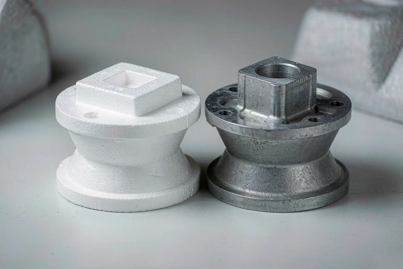
Process Windows That Control Lost Foam Casting Quality
These are the parameters buyers should see on a lost foam casting supplier’s process sheet before approving first article. Ask for the numbers in writing; if a shop cannot produce this table, expect dimensional drift between batches.
| Parametr | Typical shop window | What happens outside it |
|---|---|---|
| Expanded cluster density | 16–24 g/L | Too dense: more gas and residue, fold defects. Too light: soft pattern, bead print-through, handling damage. |
| Coating dry film | 0.3–0.8 mm, 1–2 dips | Too thin: sand fusion and metal penetration. Too thick: gas cannot vent, folds and carbon films. |
| Coating gas flux capacity | ≈1–2 cm/s superficial | Too tight: folds, pyrolysis residue. Too open: rough surface replica and burn-on. |
| Sand grain fineness | AFS 40–70, dry unbonded | Too coarse: metal penetration. Too fine: the bed itself blocks venting. |
| Compaction density | ≈1.5 g/cm³ before pour | Soft pockets: dimensional loss and sand ingress during fill. |
| Pouring temperature, A356 | 760–790 °C (710–750 °C green sand) | Too cool: folds and misruns in ribs. Too hot: penetration and coarse grain. |
| Fill time, mid-size cluster | 8–20 s | Too slow: lapped, oxidised fronts. Too fast: coating cracks and sand is aspirated in. |
| Vacuum assist | 0.3–0.6 bar below atmosphere | Too low: unpredictable front. Too aggressive: metal outruns the front and traps coating fragments. |
| Practical minimum wall | ≈4 mm aluminium, ≈5 mm grey iron | Below that: freeze-off and misrun unless the front is locally fed. |
Two items deserve a caveat. First, the slower cooling of a dry silica flask produces a coarser secondary dendrite arm spacing than a permanent mould does, so T6 response is not automatically the same as for the same alloy cast elsewhere — plan your obróbka cieplna odlewów cycle against the actual section, not the datasheet. Second, because there is no core box and no parting line, most of the dimensional scatter you are used to paying for simply disappears; the remaining tolerance sensitivity sits in pattern consistency and coating thickness, which our ISO 8062 tolerance guide covers in detail.
Lost Foam Casting vs Green Sand vs Investment Casting
Pick the process from geometry and volume first, then from price. The comparison below assumes a 0.5–10 kg part with internal galleries — the class where this decision actually gets made — read it as a decision filter, not a ranking.
| Czynnik | Lost foam casting | Odlewanie w zielonym piasku | Odlewanie precyzyjne |
|---|---|---|---|
| Tooling to first article | $8,000–$30,000 cluster tool + glue fixture, 6–10 weeks | $2,000–$8,000 pattern + core boxes, 3–5 weeks | $6,000–$25,000 die + wax and shell line, 8–12 weeks |
| Consumed per piece | Foam cluster $3–$8 (bead, glue, coat, dry) | Cores $2–$8 when required | Wax pattern + shell per piece |
| Cores for internal galleries | None — the cluster forms them | Required, with core prints and core shift | Usually none with soluble or ceramic cores |
| Draft | 0.5–1°, only to eject the cluster from its tool | 2–3° to draw the pattern from sand | Little to none |
| Parting-line flash | None | Always, and it drives cleaning cost | Minimal |
| Typical tolerance behaviour | Usually one ISO 8062 grade tighter than green sand for the same part | Baseline | Best of the three |
| As-cast surface, Ra | ≈6.3–12.5 µm | ≈12.5–25 µm | ≈3.2–6.3 µm |
| Practical minimum wall | ≈4 mm aluminium | 3–4 mm, section-dependent | 1.5–2 mm |
| Volume it suits best | Roughly 1,000–30,000 per year | 1 to tens of thousands | Any volume, high piece cost |
A note on the two processes on either side of this table. Below about 1,000 pieces the foam tooling rarely pays back and green sand stays cheaper, which is why most low-volume complex parts we quote go through conventional odlewanie w formach piaskowych or, when the surface demands it, odlewanie precyzyjne. Above the low tens of thousands, dies win. Our earlier walk-through of permanent mould casting put its break-even against sand near 1,200 pieces for a comparable part, and against high-pressure die casting near 3,000 — so the useful lost foam casting band is real, but it is a band, not the whole range.

Where the Money Is: Tooling, Break-Even and Piece Cost
Here is a worked lost foam casting example. All figures are US dollars, quoted against a green-sand baseline on the same part — the pump housing above, run in aluminium with three internal cores today.
| Pozycja kosztowa | Green sand today | Lost foam proposal |
|---|---|---|
| Pattern / tooling | $9,900 (pattern plate + 3 core boxes) | $16,000 (single-cavity cluster tool + glue fixture) |
| Tooling delta | — | +$6,100 |
| Core making and setting labour | $3.40 / pc | $0 |
| Core-fin and parting-flash removal | $1.60 / pc | $0.10 / pc |
| Shot blast and grinding allowance | $1.10 / pc | $0.50 / pc (mostly gate removal only) |
| Foam cluster consumed per shot | $0 | −$4.50 / pc (bead, glue labour, coating, drying) |
| Net per-piece saving | — | $6.10 / pc |
Break-even is then straightforward: $6,100 ÷ $6.10 = 1,000 pieces. Under a thousand units a year you are paying for tooling you will not recover; at 5,000 units the same part is about $24,400 better off, mostly because three cores and their cleaning simply stopped existing.
Two things are easy to miss when you build your own version of this lost foam casting table. Cluster pattern tools are single-cavity: if you need a rate above roughly 150–250 shots per shift, budget for a second tool rather than expecting the first one to run faster — the cycle is dominated by bead blowing and cluster gluing, not by the casting machine. And the piece saving is only real if your drawing actually exploits the process; converting a part that needs one core will not produce a $6.10 delta. If you want the deeper logic on how these drivers interact, our shop-floor cost breakdown walks through each line item, and the machining side is covered in our Usługi obróbki skrawaniem CNC.
Defects You Only Meet With Lost Foam Casting
Shrinkage, dross and general misruns behave much as they do elsewhere. The table below is the shortlist that belongs specifically to lost foam casting — names your supplier should be able to say out loud — if they do not use these words, they probably are not controlling them.
| Defect | Root cause | Practical fix |
|---|---|---|
| Fold lines / metal lapping | Fronts meeting after they have slowed and oxidised; pour too cool or fill too long | Raise pour temperature 20–30 °C, cut fill time, add vacuum, re-gate so fronts do not collide in thin ribs. |
| Carbon film / pyrolysis residue | Too dense a pattern, coating too impermeable, gas not evacuated | Drop cluster density toward 16–18 g/L, thinner coat, coarser permeability target, vacuum assist. |
| Sand fusion / burn-on | Coating too thin or cracked, coarse sand, hot spot | Second dip to reach 0.6–0.8 mm, finer AFS grade locally, reduce local superheat. |
| Bead print-through | Coarse bead class and density too low to fill it | Finer bead grade, density near the top of the window, polishing on cosmetic faces afterwards. |
| Dimensional loss in a pocket | Soft sand during compaction or a flimsy cluster section | Verify bulk density before pour, add a handling rib to the cluster, or support that region with a fixture. |
| Misrun in isolated ribs | Section below the practical wall limit for its length | Thicken to 4 mm or more, feed the front locally, or accept a different process there. |
Verification is worth specifying explicitly, because several of these only show up after sectioning or X-ray. Fold lines and carbon films are usually invisible on the skin, so put the acceptance method on the drawing rather than relying on a visual check — the options and their limits are set out in our metody kontroli odlewów guide, alongside the routine wady odlewnicze that still apply here.
When a Buyer Should Specify This Process
Lost foam casting earns its keep when several of the following are true at the same time. One or two is not enough to justify the tooling.
- You are paying for three or more cores today. Every core is a core box, a print, a setting operation and a fin to grind off. This is the strongest single signal, and it is why cylinder heads, manifolds and hydraulic blocks are the classic applications.
- Internal galleries are curved or multi-planar. Straight drilled cores are cheap to make with other routes; a maze is not.
- Annual volume is above roughly 1,000 pieces. Below that the tooling delta dominates, and below about 200 it rarely gets quoted at all.
- You can hold walls at 4 mm and above for aluminium, 5 mm and above for grey iron.
- You have six to ten weeks of tooling lead available. The cluster tool, not the casting, is on the critical path.
The counter-cases matter too, and they are why you should not treat lost foam casting as a default upgrade. If your part lives or dies on pressure tightness without impregnation, the coarser structure and slower cooling can work against you. If the drawing is dominated by thin fins under 3 mm, look at odlewanie precyzyjne instead. And if the whole geometry is a thick-section load path, ask whether casting versus forging is even the right question.
In practice the parts that convert best cluster in a few applications: pump and valve castings with cross-drilled galleries, automotive castings such as intake manifolds and brackets that consolidate several pieces into one, and aluminium castings where machining stock is currently generous because the location datums move between batches. Iron casting runs well here too — but check the next answer before you commit a ferrous part to this route.
Najczęściej zadawane pytania
Does lost foam casting really need no draft?
You still need 0.5–1° to eject the foam cluster from its aluminium tool, but you do not need the 2–3° normally required to draw a pattern out of sand. On a 60 mm deep boss that difference is roughly 1–1.5 mm less taper per face, which often removes a machining step.
Why does it have to be poured hotter?
The advancing front spends part of its superheat decomposing the foam in front of it. If you pour at the conventional green-sand temperature, the front stalls when it reaches a thin rib, and what you get is a fold line rather than a clean fill — hence the 760–790 °C band for A356 instead of 710–750 °C.
Can it run grey iron and steel?
Grey and ductile iron run routinely through lost foam casting. Low-carbon steels are harder: the casting skin can pick up carbon from the pyrolysis residue, so if your surface has to stay at specification you need roughly 1.5–2 mm of machining allowance or a different route. Raise that question before quoting, not after first article.
What tolerances should I expect?
Because there is no parting line and no core shift, the same part usually lands one ISO 8062 grade tighter than it did in green sand. From there the remaining variation is pattern-to-pattern consistency plus coating thickness. Put the numbers in the drawing and cross-check them against our tolerance reference rather than assuming a grade.
Is it more expensive than green sand?
Tooling yes, per piece usually no — once you are past the break-even illustrated above. The honest way to answer it for your own part is the tooling delta divided by the per-piece saving; anything above a volume you can actually commit to within about 18 months is a gamble.
How do I start if I only need twenty parts?
You do not need the production tool. Clusters for small runs are cut and glued from foam stock, which removes most of the tooling cost and lets you validate the design before committing. That is how to convert an existing machined or fabricated part into a casting with the risk kept low.
*Process windows referenced from AFS and Aluminum Association publications, combined with Supro MFG production records; cost figures are illustrative ranges and must be re-quoted against your own drawing.
 English
 Français
 Deutsch
 Italiano
 日本語
日本語 한국어
한국어 Polski
 Português de Angola
 Русский
 Español de Argentina