
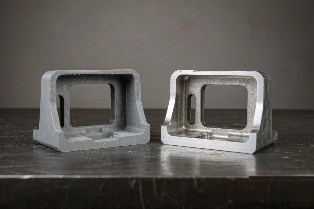
Le 3D printing vs casting question is almost never about which process is better. It is about which phase of the program you are standing in. Printed parts win on speed to first article. Castings win on unit cost, material properties and surface finish the moment volume exists. Teams that treat the choice as permanent usually end up paying for the right process at the wrong point on the curve.
This guide works through the numbers instead of the sales language. You get the real capability limits of polymer and metal printing measured against sand casting, investment casting and die casting; the breakeven math that tells you when a casting takes over; the five geometry changes a printed design needs before it can be cast at all; and the three hybrid routes that use printing for development and casting for production. Cast dimensional limits below follow ISO 8062-3, and process terminology follows the Société américaine de la fonderie standards.
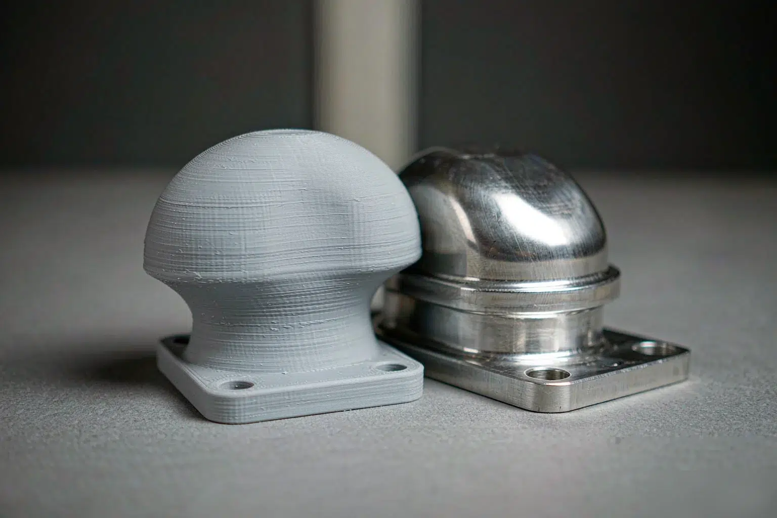
3D Printing vs Casting: The Decision Is About Phase, Not Process
Every hardware program runs through three phases, and each phase is governed by a different binding constraint. In the first phase the constraint is calendar time — you need something physical to put on a bench. In the second phase the constraint is material truth — the part must be made of the alloy the qualification plan is written around. In the third phase the constraint is cost per piece, and nothing else survives contact with the purchase order.
3D printing is structurally strong in phase one and structurally weak in phase three. Casting is the reverse. The failures happen in the handover between them, so the useful question is not which process to choose but when to switch.
Three Questions That Decide the Route
- Which property is on the critical path? If the part carries structural load, seals against pressure or operates above roughly 120 °C, a polymer print is a form-and-fit mock-up and not a functional test article. Metal printing can be functional, but the alloy choice is narrower than the cast alloy list.
- What is the 24-month quantity? Total demand across the program life, not the first order. This single figure moves the decision more than any technical parameter.
- What does the mating interface actually need? If the critical interface is subsequently machined, the as-built tolerance of the casting matters far less than buyers assume. That is covered in detail in the practical cast tolerance reference.
Answer those three and most 3D printing vs casting decisions settle themselves. Where it does not is at low volume with a demanding interface — and that is exactly where the breakeven math below earns its keep. If you are still mapping the whole process landscape, the Guide sur la fonderie des métaux is the place to start.
3D Printing vs Casting Capability Limits: Where Each Route Stops Working
The table below is the honest version of the 3D printing vs casting comparison. Every column is a hard wall, not a preference. Values are typical production figures — the tolerance grades are the ISO 8062-3 cast grades, and the printing figures are what a commercial service bureau will quote with confidence rather than what a machine brochure claims.
| Route | Tolerance | Min wall | Surface Ra | Max size | Draft |
|---|---|---|---|---|---|
| Polymer print (SLS / SLA) | ±0.25 mm | 0.8–1.0 mm | 8–12 µm | ~750 mm | none |
| Metal print (DMLS) | ±0.10 mm | 0.4 mm | 6–10 µm | ~400 mm | none |
| Moulage au sable | DCTG 8–12 | 3–4 mm | 12.5–25 µm | >1,000 mm | 1–2° |
| Moulage de précision | DCTG 6–9 | 0.8–1.5 mm | 3.2–6.3 µm | ~500 mm | 0.5–1° |
| Die casting (Al) | DCTG 6–8 | 0.8–1.5 mm | 1.6–3.2 µm | ~600 mm | 1–3° |
Read the surface row carefully, because it is where the 3D printing vs casting comparison usually gets decided by accident. A DMLS part at Ra 6–10 µm looks better than a raw sand casting at Ra 12.5–25 µm, so the printed part appears to win on quality. But the print surface is isotropic and reproducible while the sand surface is directional — and both are typically machined or blasted at the same critical interfaces anyway. Compare the finished part, never the as-built one.
Two walls in this 3D printing vs casting table deserve separate attention. The max size column kills large metal printing outright, because part geometry must fit a build envelope with support structure. The draft column is the one that costs engineering time: printed geometry has no draft and no parting line, so any design carried forward from a print must be rebuilt for casting. That rebuild is the subject of the fourth section below.
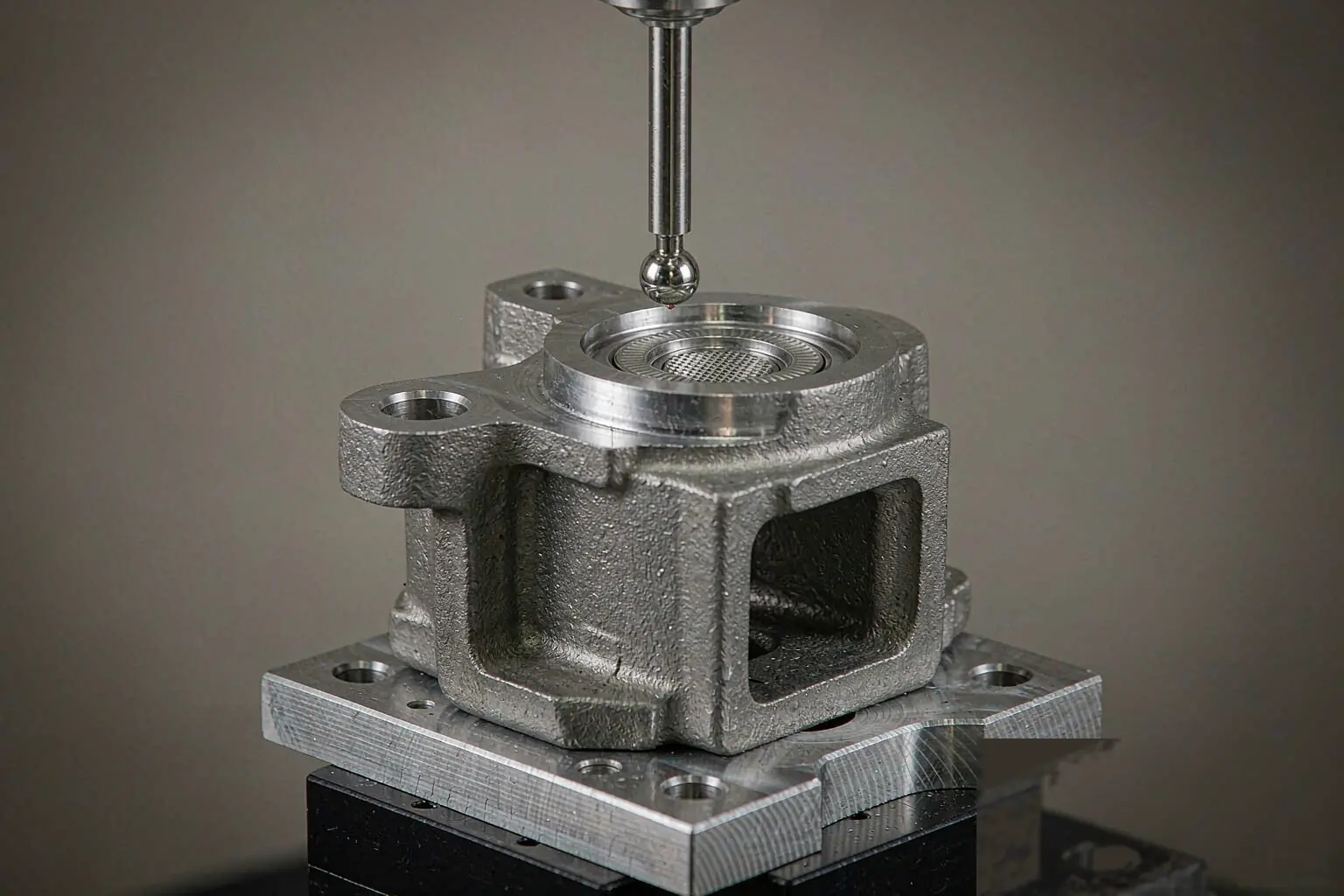
The Breakeven Math Buyers Skip
Metal printing has no tooling, so its per-piece price is nearly flat against quantity. Casting carries a tooling charge, so its average price falls steeply as volume rises. The 3D printing vs casting decision for a functional metal part therefore reduces to a single crossover point:
Breakeven volume = Tooling cost ÷ (Printed unit cost − Cast unit cost)
Below that volume, printing is cheaper. Above it, casting is cheaper — and the gap widens every time the quantity doubles. The number that surprises buyers is how small the breakeven volume usually is.
Worked Example: 1.2 kg A356-T6 Bracket
A machine bracket, roughly 180 × 120 × 40 mm, in A356-T6. Metal printing quotations land near $220 per part at any quantity. An investment casting die costs about $6,500, and the cast part lands near $38 each at 500 pieces. Breakeven is 6,500 ÷ (220 − 38) = 36 parts. At 35 pieces printing is still ahead; at 36 the casting is already cheaper on total spend, and by 500 pieces the printed route costs about four times as much.
Heat treatment is not optional on this alloy either — T6 properties come from solution treatment and artificial ageing, which is an extra step in both routes but a routine in-house one for a foundry. The T6 and stress-relief reference covers what the cycle does to dimensional stability.
Worked Example: 4 kg Ductile Iron Housing
The same bracket logic applied to a heavier part is even less forgiving. Metal printing a 4 kg ductile iron housing runs near $680 per piece, while a sand casting pattern costs about $2,400 and the cast part lands near $46 at 500 pieces. Breakeven is 2,400 ÷ (680 − 46) = 4 parts. Below four pieces a print is defensible; above four, casting is the only economical answer. Note that the cast route itself still has to be chosen — sand and investment differ enough to change both tooling and tolerance, which is what the sand casting versus investment casting breakdown works through.
| Part | Print unit | Cast route | Tooling | Cast @500 | Breakeven |
|---|---|---|---|---|---|
| 1.2 kg A356-T6 bracket | $220 | Investment | $6,500 | $38 | 36 pcs |
| 4 kg ductile iron housing | $680 | Sable | $2,400 | $46 | 4 pcs |
What the Formula Leaves Out
Four costs sit outside the 3D printing vs casting crossover calculation and all four favour casting at production volume. Secondary machining applies to both routes, but printed near-net geometry usually needs more of it, and machining is where the per-piece cost advantage of printing disappears. Engineering change cost is asymmetric: a print change is a new file, a pattern change is a tooling modification — but the printed route repeats the change on every future part, while the cast route amortises it once. Inspection cost is lower on a casting because dimensional variation is repeatable and can be sampled rather than verified piece by piece. And fixture reuse matters: the fixtures built for a cast part carry into production, so the printed phase pays for them twice.
One honest counter-argument survives the 3D printing vs casting math for the printed route: when the design is still changing weekly, paying for tooling is a bet on a moving target. That is a schedule risk, not a cost argument, and it is precisely why the hybrid routes below exist. When both routes need finish machining, the comparison narrows to near-parity — the CNC machining versus casting sequencing guide covers that case, and our finish machining service is set up to run directly off castings.
Five Geometry Changes Before a Print Becomes a Casting
This is the part of the 3D printing vs casting transition that consumes engineering hours rather than money, and the part most often underestimated. A printed file is not a casting drawing. Five changes are non-negotiable:
- Add draft on every vertical face. Roughly 1–2° for sand, 0.5–1° for investment, 1–3° for die casting. A printed file at 0° draft cannot be withdrawn from a mould without tearing the surface.
- Equalise wall thickness. Printing tolerates thick-to-thin transitions; casting does not. Heavy sections solidify last and feed from thin ones, which is how shrinkage porosity starts. Anything above about 4× the nominal wall is a candidate for coring out.
- Fillet internal corners. A practical rule is a minimum radius equal to the wall thickness. Sharp internal corners in a casting concentrate stress and produce hot tears during cooling — most of the failures in the common casting defects reference trace back to this one line item.
- Plan the parting line and cores. Internal channels that a printer builds in free space need core prints and a core that can be removed. This is a mould design decision, and it is cheaper to make it with the pattern shop than to discover it at first article — see how mould and pattern making is scoped.
- Add machining allowance, don’t chase net shape. Budget 1.5–3 mm per machined surface instead of printing to final dimension. Net-shape ambition is what drives cast tolerance arguments that were never necessary.
Budget one to two engineering days for this 3D printing vs casting geometry conversion on a typical bracket, and treat the output as a new revision with its own drawing number. Programs that skip that step end up comparing a print and a casting that were never the same part.
Three Hybrid Routes That Resolve the Trade-Off
The 3D printing vs casting argument is only a trade-off if you insist on one process for the whole program. Three hybrid routes are in routine industrial use and each one removes a specific risk.
Route 1: Printed Pattern, Sand Casting
A printed pattern replaces a wooden one for low-volume work. This is the cheapest way to take a 3D printing vs casting decision through to a real casting — correct alloy, correct solidification behaviour — for the cost of a print plus a mould, with no pattern investment. It is the standard bridge between a validated print and a production order, and it is what our sand mould casting service does for one-off and bridge quantities.
Route 2: Printed Wax Pattern, Investment Casting
Where the final process is investment casting, printing the wax pattern directly skips the wax die entirely. You get investment-cast tolerance and surface at prototype quantity while the production die is still being quoted. This route is worth it whenever the die lead time is the thing blocking the program, and it feeds straight into investment casting production once the design is frozen.
Route 3: Print for Fit, Cast for Verification
Print the mock-up to check packaging, harness routing and assembly access, then cast the same geometry for the mechanical and environmental test articles. This is the cheapest way to run two parallel workstreams, and it is how most of our prototype printing et metal prototype casting work is paired by customers.
Note the volume ceiling on all three routes. Once annual demand crosses several thousand pieces and the design is stable, die casting becomes the third phase — and that is a different cost curve again, covered in the die casting versus sand casting comparison and served by our high-pressure die casting line.
Four Gates Before You Commit to Tooling
Where both processes are technically eligible, the 3D printing vs casting risk is not choosing wrong — it is choosing late. Gate the transition so the decision stays cheap to reverse until it genuinely has to be made. NADCA publishes comparable process and cost material for die casting at nadca.com.
- Gate 1 — material equivalence. Confirm the cast alloy meets the load, temperature and corrosion case that the printed prototype was tested against. Until this is signed off, no tooling discussion is meaningful.
- Gate 2 — measurement plan. Name the method and the datum scheme for the critical interfaces: CMM, calliper or functional gauge. Tolerance arguments in the first article report are almost always measurement arguments.
- Gate 3 — design freeze with an ECO rule. Write down what counts as a change after pattern release and who approves it. This single sentence prevents the most expensive category of tooling rework.
- Gate 4 — bridge quantity. Order the printed-pattern bridge before the die arrives so the test program never blocks on tooling. Bridge quantities are usually 10–50 pieces.
Run the four gates in order and the 3D printing vs casting decision stops being a debate and becomes a scheduled step. Programs that invert the order — committing to tooling first and qualifying material later — are the ones that rebuild a pattern two months in.
FAQ
Is 3D printing cheaper than casting for one prototype?
Almost always yes for a single polymer part, and usually yes for a single metal part. The breakeven in the metal case is only tens of pieces, so the printed route only wins on the very first article — and it stops winning as soon as the tooling is amortised over a few dozen parts.
Can a printed part simply replace a casting in production?
Only if material, tolerance and surface all match the real requirement. A 3D printing vs casting substitution that ignores any one of the three fails at qualification. Polymer prints cannot substitute for a structural fonderie de métaux, and metal prints are limited by build envelope and by per-piece cost that does not fall with volume. Treat a print as a phase-one deliverable, not a production substitute.
How much draft do I have to add to a printed design?
1–2° for sand casting, 0.5–1° for investment casting and 1–3° for die casting, applied to every face that withdraws from the mould. Deep pockets and textured surfaces need more. Draft is added to the casting revision, not to the printed file.
Can you make a sand casting pattern from a printed part?
Yes, and it is the fastest bridge from a validated print to a real casting. The printed pattern is mounted on a board with the parting line and core prints added, then used for a short run — typically 10–50 pieces — while the production tooling is quoted and cut.
Which is faster to first article, 3D printing vs casting?
Printing, by a wide margin: 1–7 days against 2–4 weeks for sand casting with new tooling and 4–6 weeks for investment casting. The gap narrows dramatically on the second and third article, because the casting route reuses tooling while the printed route starts from zero every time.
*Dimensional grades per ISO 8062-3; process terminology per AFS. Unit costs are typical production figures for the part sizes stated and will move with alloy, wall thickness and inspection level.
 English
 Français
 Deutsch
 Italiano
 日本語
日本語 한국어
한국어 Polski
 Português de Angola
 Русский
 Español de Argentina