
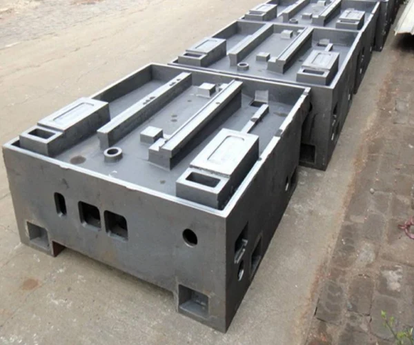
In the production of automotive aluminum castings, sand casting remains the preferred process for balancing cost and complexity. However, if the parting line location and draft angle are designed carelessly, issues such as flash and porosity may arise, directly reducing the yield rate. This article systematically outlines these key control points: a properly designed sand casting parting line must balance metal filling dynamics with gas escape pathways; standardized draft angles can effectively prevent sand grain spalling and damage to the mold walls during demolding; the use of precision guide pins and clamping systems can tighten tolerances and prevent wall thickness variations; and the combination of refractory coatings and appropriate sand grain sizes can improve the surface finish of sand castings and reduce sand adhesion defects. For thin-walled hollow structures, gradual transitions and collapsible sand cores must also be employed to balance flowability and crack resistance. The following sections will illustrate, using actual processing parameters, how to synergistically optimize these variables to ensure the stable mass production of high-precision odlewy aluminiowe.
Understand sand casting parting line selection for automotive aluminum
In complex automotive components, the layout of the sand casting parting line serves as the fundamental benchmark for determining mold assembly accuracy and dimensional repeatability. The selection of the optimal parting line directly determines how the upper and lower mold halves align, thereby affecting the overall stability of the mold during high-volume production. When mold engineers define a straight, continuous parting line along the largest cross-section, they can both minimize core positioning errors and prevent flash from forming. A well-designed sand forma odlewnicza parting line simplifies the fabrication of upper and lower mold assemblies, reduces the need for loose components, and ensures consistent quality of complex structural housings.
Primary geometric considerations for determining optimal split planes
The direction of the sand casting parting line is determined by the location of the automotive part’s largest cross-sectional contour to ensure smooth demolding of the pattern. Placing the parting line on a single horizontal plane simplifies mold assembly and prevents dimensional misalignment between the upper and lower mold boxes.
This continuous parting line minimizes the need for complex stepped molds and loose cores, thereby avoiding potential mechanical alignment errors. Establishing a clear and smooth parting line ensures strict sand casting tolerances on all critical mating surfaces.
Balancing mold filling dynamic stability and gas evacuation efficiency
During high-speed pouring of molten aluminum, the positioning of the sand casting parting line determines the path through which air and gases from the cores can naturally escape. Placing the parting line near the highest vertical point of the mold cavity allows the expelled gases to escape freely through the top vent, thereby preventing air from becoming trapped in the molten aluminum flow. Improper positioning of the parting line can obstruct the natural escape of gases, leading to turbulence as the metal flows in and the formation of internal porosity, which compromises the component’s density. To achieve optimal mechanical properties after defect-free casting, learn about our methods for [Kontrola porowatości i skurczu w odlewach piaskowych z aluminium w motoryzacji].
Optimize sand casting draft angle for flawless mold pattern release
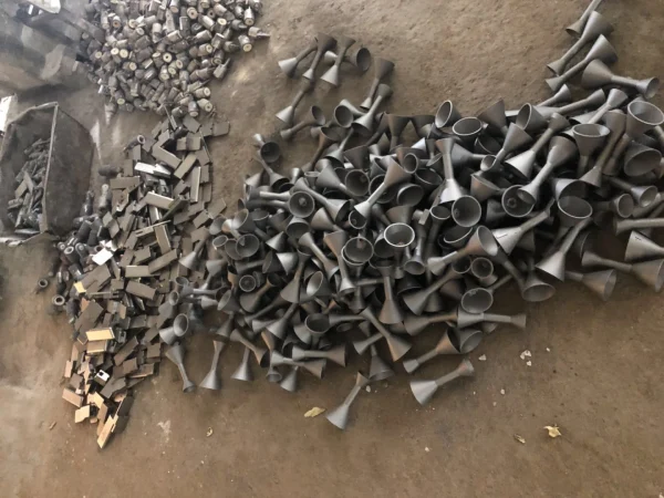
Designing the draft angle in odlewanie w formach piaskowych is a key measure to prevent localized mold fractures and surface damage during demolding. If sufficient vertical draft is not incorporated into the mold walls, physical friction during demolding will strip fragile sand particles from the surface of the mold cavity. This mechanical damage immediately contaminates the molten aluminum flow and compromises the part’s geometry. By establishing standardized draft angles for external surfaces and deep internal cavities, the structural integrity of the mold must be maintained during high-speed production. A proper demolding process ensures that castings are dimensionally accurate and have smooth, defect-free outer surfaces.
Standardizing interior and exterior angular taper specifications
Standardization requirements for draft angles in sand casting: Vertical outer walls must have a draft angle of at least 1.0 to 1.5 degrees, while deep internal cavities require a draft angle of 2.0 to 3.0 degrees. Since green sand and resin sand adhere tightly to vertical mold surfaces, shallow internal walls require larger draft angles to overcome the vacuum resistance generated during demolding. Providing sufficient draft angles prevents sand wall tearing and ensures that the sand mold cavity maintains precise geometric proportions. Adopting these standardized angle parameters allows for strict adherence to sand casting tolerances while preventing localized damage to the mold surface.
Preventing mold wall shear damage during high-volume production
Insufficient draft angle in sand casting can lead to mechanical shear stress, causing sand particles to peel away from the mold walls during automatic demolding. These loose sand particles can fall into the lower cavity of the mold, resulting in sand-washing defects and significantly reducing the surface finish of the casting. Applying a smooth micro-coating and using an appropriate draft angle can eliminate friction-induced wall wear, ensuring that the mold cavity remains intact before liquid metal is poured. Ultimately, protecting the mold walls from spalling damage not only guarantees perfect surface quality but also maintains dimensional accuracy during high-volume automotive production.
Achieve tight sand casting tolerances through precise tooling alignment
In automotive parts production, sand casting tolerances are closely related to the mechanical alignment accuracy between the sand boxes and the internal cores. When the upper and lower sand boxes shift during the mold closing process, the resulting dimensional deviations can compromise critical assembly locations and bolt hole layouts. The use of precision-ground steel guide pins, rigid mold locking devices, and automated clamping systems effectively prevents mechanical clearance at the mold joints. This strict positioning control eliminates issues such as core drift and mold displacement caused by the pressure of molten metal. Consequently, precise sand casting mold alignment ensures that every casting consistently meets international dimensional accuracy standards such as ISO 8062 CT8.
Managing dimensional variations across the mold separation joint
During the high-pressure pouring stage, the lifting of the parting line and the horizontal displacement of the sand box can have a significant impact on sand casting tolerances. When molten aluminum fills the mold cavity, hydrostatic pressure pushes the upper sand box upward, causing changes in wall thickness on both sides of the parting line. This fluid pressure can be counteracted by installing a calibrated pneumatic clamping system on the upper sand box and placing heavy weights on it, thereby preventing the sand mold from separating. By controlling vertical displacement at the parting line, strict cross-sectional dimensional accuracy can be ensured for finished automotive structural castings.
Implementing hard guide pins for high-precision core alignment
To prevent wall thickness variations in the complex internal channels of automotive components, the core must be positioned with ultra-high precision to meet sand casting tolerances. Hardened steel guide pins and hardened sleeves securely lock the core in place within the sand mold, thereby eliminating displacement during liquid metal injection. If core alignment errors are not corrected, drifting internal cores can lead to uneven wall thickness, thereby reducing mechanical strength and compromising the component’s sand casting surface finish. Integrated hard alignment components ensure that the internal channels maintain perfect concentricity even under turbulent conditions.
Improve sand casting surface finish using optimized mold coatings
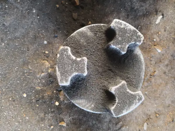
The surface finish of sand castings directly determines the aesthetic quality of high-end automotive aluminum components and their subsequent machining requirements. When molten metal at high temperatures flows into an unprotected sand mold cavity, the penetration of the liquid metal can cause severe sand sintering defects. By applying a refractory coating and controlling the sand particle size distribution, a smooth protective barrier can be formed between the molten aluminum and the sand matrix. This advanced material barrier prevents liquid metal from penetrating the microporosity of the sand particles while maintaining the necessary gas venting channels.
Applying refractory wash coatings to reduce sand burn-on
Applying alcohol-based or water-based graphite and zirconia refractory coatings to the walls of sand mold cavities significantly improves the surface finish of sand-cast parts. Spraying a layer of coating with controllable and uniform thickness prevents molten aluminum from directly fusing with silica sand particles under thermal stress. This protective thermal barrier eliminates sand grain sintering, thereby preventing the formation of rough surface inclusions and reducing the workload associated with secondary shot blasting. Maintaining a uniform coating thickness not only ensures sand casting tolerances but also gives the surfaces of complex automotive components an exceptionally clean and smooth appearance.
Balancing fine sand grain size distribution and permeability
Optimizing the surface finish quality of sand castings requires selecting the optimal AFS sand particle size value (typically AFS 55 to 65) for green sand molding. Finer sand particles pack more tightly, forming a smooth mold surface that prevents metal penetration and improves overall surface quality. However, finer sand particles result in lower mold cavity permeability; if the sand casting draft angle and venting channels are improperly designed, this may lead to gas entrapment in the core. Ensuring that the fine sand packs tightly while maintaining adequate venting prevents gas entrapment and yields a perfect surface texture.
Szukasz niezawodnej odlewni metali w Chinach?
- Możemy Ci pomóc optimize product design and save costs.
- Możemy pomóc Ci w realizacji dużych zamówień o wysokiej jakości części odlewane.
- Możemy dostarczyć na czas i zyskać więcej możliwości rynkowych sprzedaży.
- Skorzystasz na współpracy z Supro MFG odlewanie metali serwis.
Resolve sand casting design limitations in thin-wall automotive parts
When designing lightweight, thin-walled aluminum components for modern automotive applications, the sand casting process faces complex physical constraints. Thin-walled sections cool extremely rapidly, which increases fluid resistance during pouring and heightens the risk of gate overflow or hot cracks. By integrating tapered cross-sections and collapsible sand cores, foundries can overcome these geometric constraints while meeting the necessary draft angle requirements. By balancing metal flow with optimized internal tooling, foundries can effectively prevent structural defects, maintain high mechanical integrity, and ensure strict dimensional accuracy—all while meeting the target part weight.
Integrating gradual wall transitions to accommodate draft angles
In thin-walled aluminum designs, adding a sand casting draft angle may inadvertently cause abrupt changes in wall thickness, thereby altering the flow dynamics of the molten metal. Introducing a taper at ultra-thin cross-sections increases local mass; if the wall thickness transition is not handled smoothly enough, hot spots may form. These abrupt cross-sectional changes increase fluid turbulence during pouring, leading to premature solidification or casting defects in adjacent thin-walled areas. A gradual taper design ensures uniform metal filling while maintaining tight tolerances. To achieve optimal mechanical properties following a defect-free pour, please review our approach to [Wytyczne dotyczące minimalnej grubości ścianek w odlewaniu piaskowym konstrukcji aluminiowych stosowanych w przemyśle motoryzacyjnym].
Utilizing collapsible sand cores for complex internal hollow features
The design of sand castings for automotive hollow structures relies on resin-bonded sand cores with high thermal strength and rapid disintegration properties. During the solidification of molten aluminum, the sand core must maintain rigidity under fluid pressure while being able to disintegrate rapidly as the metal contracts during cooling to prevent thermal tearing. Poor disintegration performance of the sand core can lead to dimensional inaccuracies and compromise the surface finish of the sand casting within critical flow channels. The use of an optimized organic binder system ensures that the sand core can be easily knocked out mechanically after cooling, leaving clean internal runners that meet stringent automotive engineering standards.
Skontaktuj się z firmą Supro MFG
This paper systematically analyzes the logic behind the coordinated optimization of core process steps in the sand casting of automotive aluminum parts, including parting line selection, draft angle setting, tolerance control, and surface treatment. A well-designed parting line must balance filling dynamics with venting efficiency, while standardized sand casting draft angle effectively prevent shear damage to the mold walls during demolding. Achieving tight tolerances through precision guidance and positioning, combined with a balance between refractory coatings and sand particle size to enhance sand casting surface finish quality, can systematically address the design limitations of thin-walled structures. The coordinated optimization of these process parameters directly drives improvements in the yield rate and dimensional consistency of complex components.
Supro MFG is committed to providing high-precision aluminum sand casting solutions for automotive OEMs and Tier 1 suppliers. Our engineering experts will optimize mold designs strictly in accordance with your tolerance and geometric requirements. Please contact Supro MFG to review your drawings so we can work together to enhance product quality.
 English
 Français
 Deutsch
 Italiano
 日本語
日本語 한국어
한국어 Polski
 Português de Angola
 Русский
 Español de Argentina