
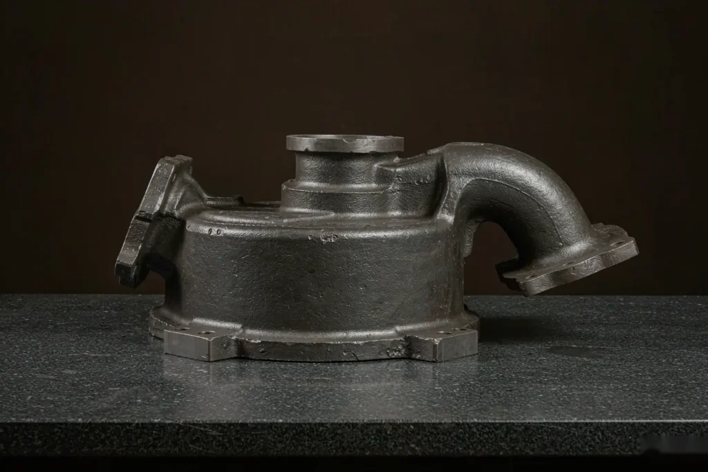
A casting tolerance stack is arithmetic with teeth. Your print calls ±0.5 mm on a flange face, the raw casting shows up with ±1.2 mm of as-cast variation, and nobody broke a rule — nobody ever added up the pieces. Build the casting tolerance stack before you quote the part, and you will know to the dollar which number is worth paying for.
This guide uses one real part — a 14.2 kg finished ductile iron pump housing running 6,000 pieces a year — and walks the same casting tolerance stack a buyer actually has to close. Every figure below is calculated from a stated assumption, not quoted from memory, so you can rebuild it with your own numbers. Where a rule carries legal weight we point at the standard itself: the datum, datum target and projected tolerance zone rules come from ASME Y14.5 dimensioning and tolerancing, the die casting guidance comes from NADCA, and measurement traceability practice follows NIST.
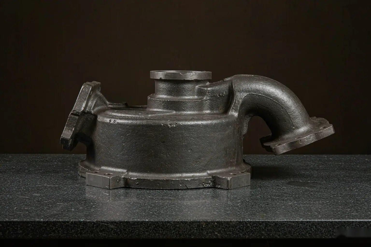
What a Casting Tolerance Stack Really Adds Up
Most buyers treat “casting tolerance” as one number — usually whatever sits in the foundry’s general note. It is not one number. It is four different sources that behave in four different ways, and only one of them is random. Our guide to casting tolerances and ISO 8062 classes covers the classification system; this article covers what those classes do once the part meets an assembly.
| Layer | Typical on a 240 mm iron housing | Behaviour |
|---|---|---|
| As-cast size and form variation | ±1.2 mm over 240 mm | Random within the batch; grows with core shift and mold opening |
| Pattern and tooling drift | +0.3 to +0.5 mm across a pattern life | One-direction drift, not noise — it moves the mean |
| Cleanup machining | ±0.10 mm per setup | Replaces the casting number on every face it touches |
| Heat treatment movement | ±0.20 mm per 100 mm on steel grades | Appears only after stress relief or normalising |
| Assembly mate | ±0.15 mm hole spacing | Adds at the joint, outside your supplier’s control |
The classic failure is treating all five rows as interchangeable. They are not. Machining replaces a casting number; it does not add to it. Tooling drift moves the centre of the distribution, which is why a process can sit inside tolerance on Monday and fail on the far side of the same tolerance six months later. And the assembly mate belongs to somebody else’s drawing — but it still lands in your casting tolerance stack.
The one-line version
Pick the surfaces you will machine, let those carry the datums, and give every as-cast surface a tolerance it can actually hold without machining. Everything else in this article is just the arithmetic behind that sentence.
Why Castings Need Different Datums Than Machined Parts
A machined block gives you three faces that are genuinely flat and square. An as-cast surface does not. Sand-cast skin carries ripple, parting-line step and core shift, so a full-face primary datum “rocks” on the fixture and every downstream measurement picks up that rocking as if it were part geometry.
- Do not datum the whole face. Call small machined pads and use datum targets. ASME Y14.5 permits targets specifically because irregular surfaces cannot seat on a full plane.
- Put datums where the metal is stable. Pad location drives the machining allowance and, later, the fixture design. A pad over a thin rib will deflect under clamping.
- Separate machined from as-cast callouts. Anything leaving the foundry untouched should be controlled by profile; anything machined can take position, perpendicularity and size.
- Check the material before you tighten. Alloy choice sets how much a section moves during heat treatment, and hence how much of your stack is recoverable.
All four decisions above are free on the drawing and expensive after tooling is cut. Pad layout in particular belongs inside the pattern and mold build, where moving a pad by 20 mm costs minutes rather than a tooling modification later.
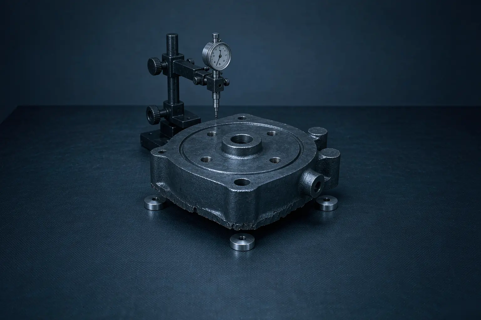
Casting Tolerance Stack Step 1: Place Your Datum Targets So They Actually Work
Target placement is usually the largest single term in any casting tolerance stack, and it is the cheapest to fix. Assume the raw housing’s datum face carries 0.8 mm of peak-to-peak form deviation, and the part body is 240 mm long. If you seat it on three targets spread over 110 mm, the same 0.8 mm error rotates the part much harder than if those targets sat 210 mm apart. Treating the form error as a single bow across the target span, the induced angle is the form error divided by the span, and the throw-out at the far end of the part is that angle times the part length.
| Datum target layout | Span / part length | Throw-out at far end | Out of a 1.0 mm budget |
|---|---|---|---|
| Three targets, cramped together | 110 / 240 mm = 45.8% | 0.8 × 240 ÷ 110 = 1.745 mm | Already over by 0.745 mm |
| Three targets, spread out | 210 / 240 mm = 87.5% | 0.8 × 240 ÷ 210 = 0.914 mm | 0.086 mm left |
The gap between those two rows is 0.83 mm of budget burned purely by where you drew the targets — with no change to the casting, the fixture or the machine. That is why the working rule is three datum targets spanning at least 70% of the datum feature’s greatest dimension. Both rows above use the same casting and the same form error; only the drawing differs.
When the layout is genuinely uncertain, prove it on a prototype casting before committing production tooling — one sample that seats badly is far cheaper than a fixture that measures the wrong thing for a year. Size the targets for contact pressure too. Three Ø10 mm pads give 236 mm² of contact area; at 1,200 N of clamping force that is 5.1 MPa, comfortably below the compressive capacity of ductile iron. Drop to two Ø6 mm spots and the area falls to 57 mm², lifting pressure to 21.2 MPa — a four-fold increase that will start marking the cast skin. Targets that are too small do not just locate badly, they damage the datum they are supposed to measure from.
Casting Tolerance Stack Step 2: Buy Cleanup Before You Buy Scrap
Every machined face must remove enough metal to clear the as-cast deviation plus fixture repeatability. With a ±1.2 mm general casting tolerance the total spread across a face is 2.4 mm, and say the fixture locates within 0.15 mm. The honest allowance is half the spread plus the fixture term: 1.20 + 0.15 = 1.35 mm, so specify 1.5 mm per side. Our machining allowance guide derives the same figure from the standard tables.
What happens when the drawing calls 1.0 mm
Cleanup only succeeds while deviation stays below the allowance minus fixture error: 1.0 − 0.15 = 0.85 mm. Modelling the as-cast deviation as uniform across ±1.2 mm, the chance of exceeding 0.85 mm on either side is (1.20 − 0.85) ÷ 2.4 = 14.6%. At 6,000 pieces a year that is 875 parts arriving with black skin.
Assume 70% can be rescued by extra grinding at $24 each and 30% are scrap at $186 of part value. Expected cost per event is 0.70 × $24 + 0.30 × $186 = $72.60. Annual exposure: 875 × $72.60 = $63,525.
What the extra 0.5 mm of allowance costs
Going from 1.0 mm to 1.5 mm on two faces of 45,000 mm² each removes another 45 cm³ of iron per part — 0.32 kg at 7.1 g/cm³, or $0.27 of metal at $0.85/kg. The money is not in metal, it is in time. Roughing that extra depth typically costs one additional face-mill traverse per surface: a 150 mm cutter needs 300 mm of travel per face at 400 mm/min, so 0.75 min each and 1.5 min per part. At a $72/hour machine rate that is $1.80 per part, or $2.07 with metal included — about $12,429 a year.
| Allowance per side | Black-skin risk | Added cost / year | Verdict |
|---|---|---|---|
| 1.0 mm | 14.6% — 875 parts/year | $63,525 of failure cost | Reject — false economy |
| 1.5 mm | Effectively zero | $12,429 | Specify this |
| 3.0 mm | Effectively zero | About $32,400 and no added quality | Reject — you are paying to machine air |
The break-even point is worth writing into your drawing notes. Paying $12,429 to eliminate failures is worth it as long as the failure rate exceeds 12,429 ÷ (6,000 × $72.60) = 2.85%. Below that, accept the occasional touch-up; above it, buy the metal. Most under-allowanced castings sit nowhere near 2.85% — they sit somewhere between 8% and 20%, which makes this one of the cheapest fixes available on any casting tolerance stack.
Casting Tolerance Stack Step 3: Write Position and Projected Tolerance Correctly
Take a bolt flange with 4 × Ø11 mm clearance holes taking M10 bolts into tapped holes in the housing. The floating fastener formula gives the total positional budget: clearance hole minimum minus fastener maximum, so 11.0 − 10.0 = 1.0 mm. Split evenly between the two parts, the cast side has 0.50 mm to work with — which sounds generous until you add height.
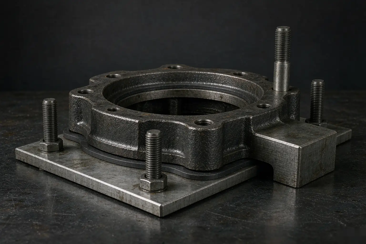
The tapped hole is 20 mm deep, and the mating lug sits 34 mm above the casting surface. Within its own tolerance zone the axis may tilt by the zone divided by its depth: 0.50 ÷ 20 = 0.025 mm per mm. Extrapolated to the projected height, that tilt becomes 34 × 0.025 = 0.85 mm of offset at the top. Add the half-zone of 0.25 mm and the worst-case radial excursion is 1.10 mm — against an available radial clearance of only (11.0 − 10.0) ÷ 2 = 0.50 mm. The drawing assembles perfectly on paper and jams on the line.
| Fix | Required position tolerance | Cost | Comment |
|---|---|---|---|
| As drawn — Ø11 clearance, 0.50 at MMC | Fails: needs 1.10 mm, has 0.50 mm | Assembly rework | Do not ship this |
| Tighten the tapped holes | 0.50 ÷ (0.5 + 34/20) = 0.227 → specify 0.20 | CNC rigid tapping instead of jig drilling; roughly $1.60/part ≈ $9,600/yr | Works, but you pay for it every part |
| Enlarge clearance holes to Ø12.5 | 1.25 ÷ 2.20 = 0.568 → 0.50 is fine | $0 in the mating part | Do this first |
Note the asymmetry of the last two rows. Checking the cheap side first — be it a clearance hole, a machined pad, or a process change to fundición a presión — usually costs nothing, while a tightened callout gets paid for on every piece forever. Before tightening any callout inside a casting tolerance stack, always check whether the cheaper half of the equation is available — often it is just a clearance hole somewhere else.
Profile of a Surface Beats Three Stacked Callouts
It also keeps the casting tolerance stack simple: one tolerance zone instead of three overlapping bands that each need their own inspection setup. On an as-cast surface, this single callout is the workhorse. Profile bounds form, orientation and location at the same time, which is exactly what you want when the surface is not precisely any of those things individually. It also inspects cleanly with a scan rather than three separate setups.
- Use it with datums when the surface mates. A profile of 1.5 mm to A|B|C bounds the whole envelope, where flatness alone would let orientation wander.
- Use the U modifier when a wall must stay thick. A 6.0 mm wall under a plain 1.5 mm profile can legally fall to 5.25 mm. Bias the zone outward with U0.75 and material only grows, so minimum wall holds at nominal.
- Leave non-critical skin uncontrolled or loosely controlled. Tightening profile there buys nothing and raises the casting cost for every piece.
- Know when to change process instead. If a sealing face needs profile tighter than sand casting can hold, switching to fundición a la cera perdida is often cheaper than machining a poor-quality skin on every part.
MMC bonus on a bore datum
On machined bores used as datums or as bolt features, specifying position at maximum material condition returns real tolerance you have already paid for. An Ø62 H7 bore with 0.20 mm positional tolerance at MMC gains the amount the bore departs from its smallest size.
| Bore produced at | Bonus | Effective tolerance |
|---|---|---|
| Ø62.000 (MMC) | 0.000 mm | 0.200 mm |
| Ø62.018 | 0.018 mm | 0.218 mm |
| Ø62.030 (LMC) | 0.030 mm | 0.230 mm |
The reverse also holds: where roundness or sealing contact governs rather than assembly, call RFS and skip the bonus. Writing MMC by habit on every hole is how parts pass a gauge and still leak.
Worst-Case or RSS? Do Not Guess
Once the terms are listed the instinct is to add them. Summed worst-case gives 1.20 + 0.10 + 0.20 + 0.15 = 1.65 mm. Root-sum-square gives √(1.20² + 0.10² + 0.20² + 0.15²) = 1.23 mm, apparently buying 0.42 mm of budget for free. It is not free, and on the as-cast term it is downright unsafe: pattern wear is a one-direction drift, not noise, so it does not average out.
| Chain term | Value | Safe to RSS? |
|---|---|---|
| Casting general dimension | ±1.20 mm | No — includes tooling drift |
| Machining allowance variation | ±0.10 mm | Yes |
| Bore position versus datums | ±0.20 mm | Yes |
| Mating frame hole spacing | ±0.15 mm | Yes |
| Hybrid: casting held worst-case, rest RSS | 1.20 + √(0.10² + 0.20² + 0.15²) = 1.47 mm | Recommended |
Pick the rule before you release the drawing, because the casting tolerance stack changes shape the moment you move from worst-case to RSS. The honest hybrid saves 0.18 mm instead of 0.42 mm. Take it if you need it, but only after you have verified with real process data that the machining terms are independent and centred — otherwise you are doing statistics on a distribution nobody has measured. Confirm it with a capable supplier in the way our supplier audit checklist describes.
What a Casting Tolerance Stack Costs When You Skip It
Here are the three decisions above on one page. Each follows the same pattern: the expensive-looking option is usually the cheapest, because failure cost dwarfs the cost of doing it right the first time.
| Decision | Do nothing | Do it right | Net at 6,000/yr |
|---|---|---|---|
| Datum target span | 1.745 mm throw-out, over budget | 0.914 mm throw-out | 0.83 mm of budget, free |
| Machining allowance | 875 failures = $63,525 | 1.5 mm = $12,429 | Save about $51,100 |
| Projected tolerance zone | Jams: 1.10 mm vs 0.50 mm | Ø12.5 clearance holes, $0 | Avoid $9,600 of tapping |
None of these required a better foundry. The first two are drawing changes; the third is a hole size in somebody else’s part. That is the real lesson of a casting tolerance stack: most of it is decided long before anyone pours metal, and it is decided by whoever writes the drawing.
Drawing Checklist Before You Send the RFQ
Ten items, each one a place where the casting tolerance stack quietly grows by another term nobody budgeted, and where a missing line turns into a phone call three weeks later. Pair the drawing with the data set in our casting RFQ guide.
| Item | What to write | Why it matters |
|---|---|---|
| 1. Machined datum pads | Pad size and location on the casting drawing | Without pads there is nothing stable to measure from |
| 2. Datum target sizes | Three Ø10 targets spanning over 70% of the feature | Over 0.8 mm of throw-out either way |
| 3. Machining allowance | Derived value, not a round habit number | Under buys scrap, over buys machine time |
| 4. General casting tolerance | ISO 8062 class plus “unless stated” | Stops every un-dimensioned surface from becoming critical; check the class against your fundición en arena route first |
| 5. Profile on as-cast surfaces | Profile to datums; add U where walls must stay thick | Replaces three stacked callouts |
| 6. Position at MMC or RFS | MMC for fasteners, RFS for sealing bores | Habitual MMC is how parts pass and still leak |
| 7. Projected tolerance zone | Zone height equal to mating thickness | Catches the jam the paper drawing misses |
| 8. Parting line and ejector limits | Bands where mismatch or witness marks are acceptable | Avoids cosmetic disputes at first article inspection |
| 9. Test coupons and their location | Separately cast or attached, and which properties apply | Prevent disagreements about which result represents the part |
| 10. Secondary operations | Which dimensions apply before and after heat treat or coating | Coating thickness from surface treatment and heat movement will otherwise land in your stack |
If you are unsure whether a given callout is achievable in the process you plan to quote, run it past the foundry before release rather than after a failed sample. A short conversation about solidification simulation is cheaper than a second tooling round.
Where to Go Next
Three habits cover most of the risk on any casting tolerance stack. First, draw datums only on surfaces you intend to machine, and space the targets wide. Second, derive the machining allowance instead of copying one from the last drawing. Third, check the height at which your position tolerance actually has to work — most jams are projected zone problems, not position problems.
From there the work branches. Process selection changes everything above, so compare routes in our Guía de fundición de metales before you finalise the drawing. If the part is a candidate for combining several pieces into one, our article on casting part consolidation shows how the same break-even arithmetic applies. And if the numbers above do not fit your geometry, ask for them to be rebuilt on your actual part — that is the whole point of the exercise.
Preguntas frecuentes
How tight can a casting tolerance stack get without machining?
For sand casting in the 240 mm range, plan on about ±1.2 mm general capability and treat anything tighter as a machining operation rather than a casting tolerance. Processes differ — see how much tighter each process can hold before you write the number.
Should I put GD&T on as-cast surfaces at all?
Yes, but keep it to profile of a surface against datums set on machined pads. Position, perpendicularity and runout belong on machined features. Putting machined-style controls on as-cast skin is the fastest route to a drawing nobody can inspect.
Do I need both ISO 8062 and GD&T on the same drawing?
Yes, and they do different jobs. ISO 8062 classes cover every dimension you did not bother to tolerance; GD&T covers the features that actually assemble. As-written defaults are why unlabelled surfaces turn into arguments — a point covered at length in our casting quality agreement article.
Who pays when the stack fails at assembly?
Whoever owns the drawing usually owns the outcome. If the casting meets its general tolerance and your machining cannot clean up, the allowance was too small — that is a design cost, not a supplier defect. Put allocation in writing before the first shipment.
What should I send so the foundry can check my stack?
The full assembly context, not just the casting drawing. Mating part tolerances, fastener sizes, projected heights and clamp locations all feed the calculation. A supplier that offers CNC machining services can close the loop internally and tell you where the stack actually fails.
*Figures calculated from the stated assumptions in this article: 6,000 pieces/year, $72/hour machine rate, $0.85/kg iron. Replace with your own volumes and rates before quoting.
 English
 Français
 Deutsch
 Italiano
 日本語
 한국어
 Polski
 Português de Angola
 Русский
 Español de Argentina