
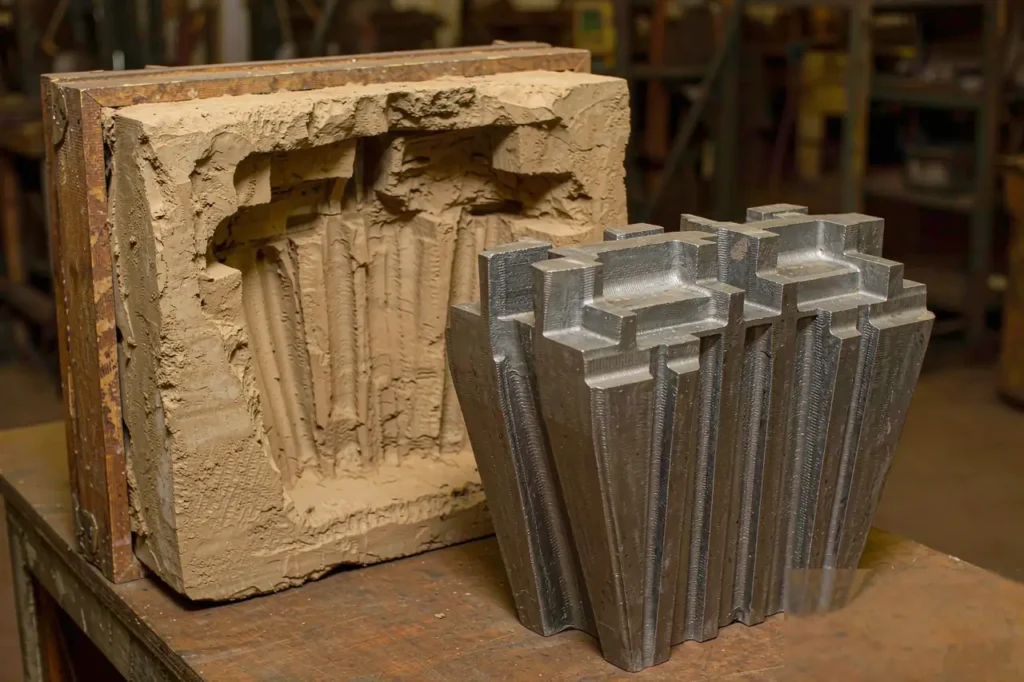
Most casting quotes fail long before metal is poured. They fail in casting mold design — the week of decisions about draft, parting line, shrink rule and core prints that quietly locks in your scrap rate, your machining bill and your tooling budget for the next five years.
This is a shop-floor guide to those decisions. Every number here is one we actually use: draft angles by process, the patternmaker’s shrink rule in both imperial and metric, the buoyancy math that decides whether a core floats, and the four-gate review we run before any pattern gets cut. Where the industry has a written standard, we cite it — the American Foundry Society (AFS) for sand practice and NADCA for die casting. Everything else comes from our own production records across fundição em areia, fundição à cera perdida and die casting programs.
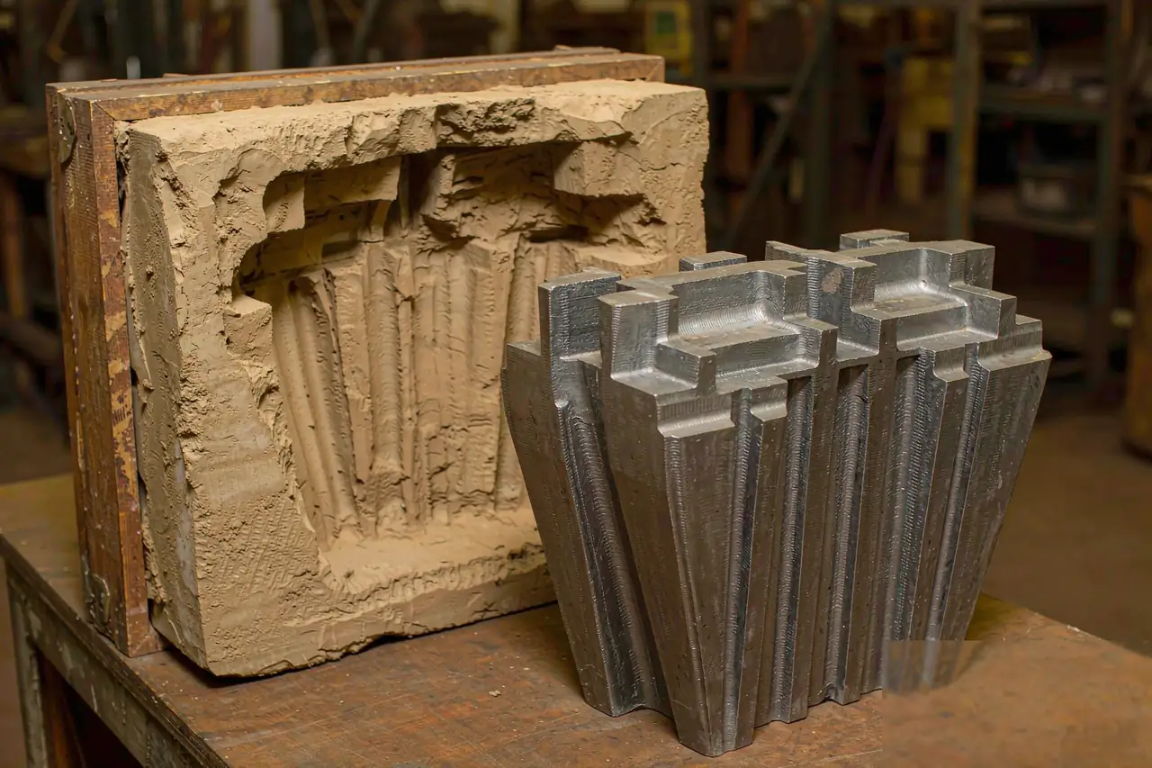
What Casting Mold Design Actually Controls
Tooling is usually 5–15% of a program’s total spend, but the geometry it encodes drives 60–80% of downstream cost. That is the asymmetry buyers miss when they shop a pattern quote on price alone. Four variables do most of the work:
- Draft. Too little and you tear the mold wall every cycle; the repair sand ends up as inclusions in your casting. Too much and you pay for metal you will machine off.
- Shrink rule. Get it wrong by 0.5% on a 600 mm steel housing and you are 3 mm short — often unreachable by machining.
- Parting line. It decides where flash forms, where mismatch shows up, and how many cores you need.
- Core strategy. Every internal cavity costs a core, a core box, a set of prints and a venting path.
If you are new to the process families these decisions sit inside, start with our guia de fundição de metais, then come back to this page for the tooling layer.
Draft Angle: The Cheapest Tolerance You Will Ever Buy
Draft is the first item in any casting mold design review — the taper on every vertical face that lets the pattern leave the mold (or the casting leave the die) without dragging sand or galling steel. It is free to design in and expensive to recover later.
| Processo | External draft (per side) | Internal / cored draft | Typical tooling |
|---|---|---|---|
| Green sand casting | 1.0°–2.0° | 2.0°–3.0° | Wood or aluminum pattern |
| Fundição por cera perdida | 0°–0.5° | 0.5°–1.0° | Wax die (aluminum or steel) |
| Permanent / gravity mold | 2.0°–5.0° | 3.0°–5.0° | Cast iron or H13 steel mold |
| Fundição sob alta pressão | 0.5°–1.5° | 1.0°–2.0° | Hardened H13 die |
The draft you add is metal you pay for
Do this arithmetic before you accept a draft number. On a sand-cast side wall 120 mm deep at 1.5° of draft, the taper adds 120 × tan(1.5°) = 120 × 0.0262 = 3.1 mm of extra wall thickness at the parting line. On a 400 × 300 mm footprint with four such walls, that is roughly 4–6 kg of extra iron per casting, every single pour. Machining it away costs a second operation; leaving it costs mass. The honest answer is usually: draft what must be drafted, machine the few faces that truly need to be square, and let the rest taper.
A useful rule from the floor: interior surfaces always need more draft than exterior ones, because the sand that forms a cavity is a projecting mass that has to survive being stripped. That is why the table above roughly doubles internal draft for every process.
Shrinkage Allowance: The Shrink Rule, Not a Guess
Liquid metal contracts as it cools to room temperature, so the mold cavity must be built oversize, and it is the second variable every casting mold design fixes. The classical patternmaker’s shrink rule expresses that as inches of allowance per foot of pattern — a system older than CAD and still accurate enough to quote from.
| Alloy family | Shrink rule (in/ft) | Allowance (%) | Pattern size for a 500 mm part |
|---|---|---|---|
| Gray iron | 1/8 | 0.8–1.0% | 505.0 mm |
| Ductile iron | 1/16–1/8 | 0.4–1.0% | 502.5–505.0 mm |
| Carbon / low-alloy steel | 1/4 | 2.0–2.4% | 510.5 mm |
| Stainless steel | 5/16 | 2.4–3.0% | 513.0 mm |
| Aluminum (Al-Si, e.g. A356) | 5/32 | 1.1–1.4% | 506.3 mm |
| Brass / bronze | 3/16 | 1.3–1.8% | 507.8 mm |
Free shrink is not the shrink you get
Those percentages are free contraction measured on an unrestrained bar. A real casting is restrained by cores, by the mold wall, and by its own thick-to-thin transitions — so effective shrink runs 20–40% below the free value on heavily cored or rigid geometry. This is the single most common reason a first-article dimension comes back long. It is also why experienced foundries run a 1–5 piece sample lot, measure, and only then adjust the tool. If you are comparing processes, note that the same restraint effect is what drives the dimensional spread discussed in our guia de tolerâncias de fundição.
Parting Line: Where Flash and Mismatch Live
The parting line is the plane where the mold halves separate, and in casting mold design it is decided earlier than most engineers expect — usually before gating, because it constrains everything downstream. Choose it badly and you create a stepped parting that needs hand-finishing on every part, or you strand a feature on the wrong side and need an extra core.
- Keep it in one plane where you can. A flat parting on a single joint costs the least to tool and the least to clean.
- Put critical dimensions on one side. Any dimension that crosses the joint inherits mismatch.
- Budget for mismatch explicitly. On a 400 mm sand casting held to ISO 8062-3 DCTG 8, the general tolerance band is about ±2.0 mm; foundries typically reserve 25–40% of that band for cross-joint mismatch alone.
Our dedicated write-up on parting line selection covers the stepped and offset cases in detail.
Cores and Core Prints: The Math Behind a Floating Core
Any internal passage, undercut or hollow needs a core. The core sits in the mold on core prints — recesses formed by the pattern that hold it in position. The failure mode is not subtle: molten metal is roughly 4.5× denser than a silica-sand core, so the core wants to float.
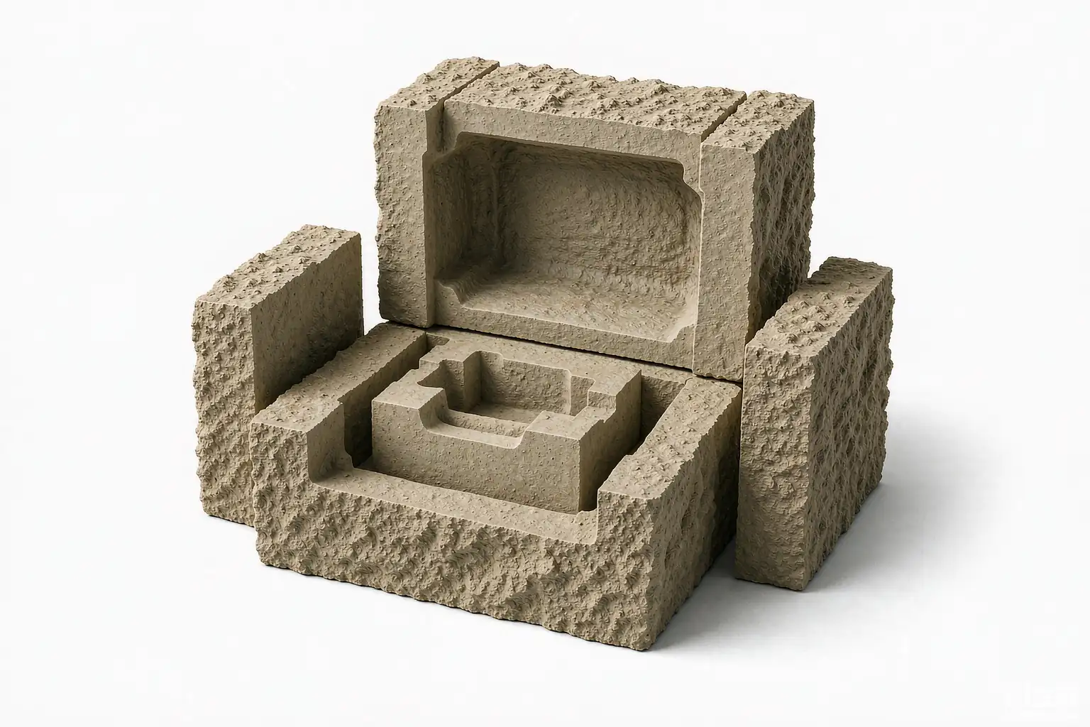
Run the numbers on a 0.5-litre silica core in gray iron. Metal density ≈ 7,200 kg/m³, core density ≈ 1,600 kg/m³, so the net uplift is (7,200 − 1,600) × 0.0005 × 9.81 ≈ 27.5 N — about 2.8 kgf pushing up, while the core itself only weighs 0.8 kg. Green sand carries roughly 70 kPa in compression; apply a 4× safety factor and you need about 27.5 × 4 / 70,000 = 0.00157 m², i.e. ≈ 1,570 mm² of print bearing area — call it a 40 × 40 mm print — to hold that one core down. Double the core volume and you double the print or you add chaplets.
Two consequences buyers should push back on in any casting mold design review: cores that are too long for their prints will shift (giving you a wall that is 2 mm thick on one side and 8 mm on the other), and cores with no vent path through the print will blow gas into the metal. Our separate piece on concepção de núcleos para fundição em areia goes deeper on venting and chaplet placement. Today, complex cores are also frequently printed rather than blown — see what changes in 3D printed sand molds and cores.
Wall Thickness, Ribs and Machining Allowance
Section thickness is the third leg of casting mold design. Uniform walls freeze uniformly; varying walls create hot spots that shrink into cavities. Practically, that means: keep adjacent sections within a 2:1 thickness ratio, blend transitions with a fillet radius of at least 0.5× the thinner wall, and keep ribs and bosses at 0.6–0.8× the nominal wall so they do not become isolated hot spots.
Minimum as-cast wall depends on the process: roughly 3–5 mm for green sand, 1.5–3 mm for investment casting, and 1.5–2.5 mm for high-pressure die casting. Anything thinner needs a process change, not a tighter tool. On top of that, add machining allowance — typically 1.5–3 mm for sand castings under 300 mm, 3–6 mm for large steel sections, and 0.5–1.5 mm for investment and die cast parts. Skimp here and you will discover the hard way why shrinkage porosity clusters just below machined surfaces.
Four Gates Before You Cut Steel
We run this review on every new tool, and we ask customers to run it with us — a casting mold design that clears all four gates rarely surprises anyone at first article. It catches about 80% of the problems that would otherwise surface at first sample.
| Gate | Question | Fail looks like |
|---|---|---|
| 1. Release | Can every face leave the mold at the specified draft? | Torn mold walls, sand inclusions, crushed edges |
| 2. Feed | Is there a directional solidification path to a riser? | Internal shrinkage, centreline porosity |
| 3. Support | Do core prints and chaplets hold against buoyancy? | Core shift, uneven walls, chaplet fusion marks |
| 4. Measure | Is there a stable datum that does not cross the parting line? | Mismatch in every CMM report |
Casting Mold Design Cost: What the Tooling Actually Buys
Pattern and mold cost scales with process and expected shots, and it amortizes over your volume. Typical ranges we quote: a single-cavity wood or 3D-printed pattern for prototypes runs a few hundred to a few thousand dollars; an aluminum matchplate for green sand production sits in the low five figures; a hardened H13 die casting tool starts in the tens of thousands. Because that spend is front-loaded, tool-friendly geometry pays for itself — as our breakdown of what drives casting cost shows, the tooling line often decides whether a 500-piece program is profitable at all.
This is also where process choice bites. If your annual volume is under a few hundred pieces, a 3D printed sand mold or a prototype casting route avoids tooling entirely; above a few thousand, the per-piece saving from a production tool in fundição sob pressão dwarfs the tool cost. And remember that the surfaces you cannot cast clean will eventually land on a machine — see CNC machining services for what that second operation adds.

Perguntas frequentes
How much draft does a sand casting really need?
For green sand, plan 1.0–2.0° per side on exterior faces and 2.0–3.0° on cored or internal faces. Deep pockets above about 150 mm benefit from the upper end of that range. Textured or hand-rammed molds need more than machine-molded ones.
Why is my first article casting dimensionally long?
Almost always because the shrink allowance in the casting mold design was applied as free shrink rather than effective shrink. Cores, mold restraint and thick sections all reduce real contraction by 20–40%. The fix is a measured sample lot and a tool correction, not a machining workaround.
Can I design a part with zero draft?
Not for sand or permanent mold casting. Investment casting tolerates 0–0.5° because the ceramic shell is broken away rather than stripped, which is one reason complex near-net shapes often move to that process. If you need square faces, draft them and machine them.
Do I need a core for every internal cavity?
Every cavity the pattern cannot form by withdrawal needs a core, and each core adds a box, a set of prints and a vent path to your casting mold design. Sometimes a redesign removes it: opening a pocket to one face, or splitting the casting into two simpler pieces, can eliminate a core box entirely and save both tooling and per-piece cost.
How early should the foundry see my model?
Before you freeze the geometry. Draft, parting line and shrink interact with the design intent, and changes made at the 3D model stage cost nothing — the same changes made after the pattern is cut cost weeks and money. Send a step file and your annual volume; a good partner will come back with a marked-up casting mold design proposal.
*Shrink rules and draft values referenced from AFS (afsinc.org) and NADCA (nadca.com) foundry practice; dimensional grades per ISO 8062-3. Buoyancy and print-area figures calculated from Supro MFG production data.
 English
 Français
 Deutsch
 Italiano
 日本語
日本語 한국어
한국어 Polski
 Português de Angola
 Русский
 Español de Argentina