
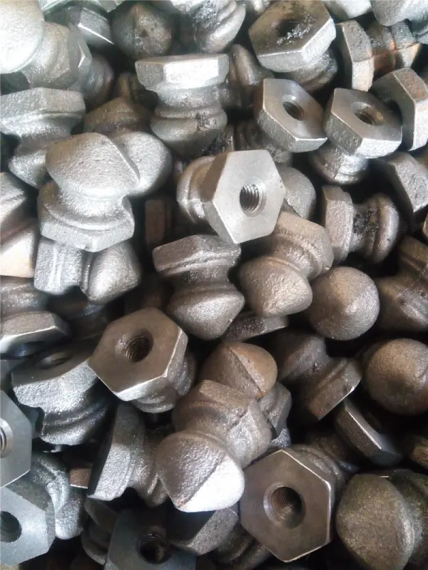
As the trend toward automotive weight reduction continues to gain momentum, sand casting has taken on a central role in the production of aluminum alloy components, and the selection of the parting line often directly determines the success of the mold and the yield rate of the castings. This article systematically describes the process for determining sand casting parting line: starting with geometric contour analysis to select straight or stepped parting lines that minimize flash and mold wear; balancing the depths of the upper and lower cavities to stabilize filling and cooling; setting a reasonable sand casting draft angle to ensure smooth demolding and prevent damage to the mold walls; and reserving machining allowances while controlling clamping force to achieve tight tolerances; Finally, prototype aluminum sand casting are used to validate the gate and riser layout, identifying flow and venting issues in advance to mitigate the risk of shrinkage porosity during mass production. These steps are interdependent and directly impact post-processing costs and assembly accuracy. The following sections will break down, based on engineering experience and operational details, how to quickly identify the optimal solution in actual design practice.
Determining optimal parting lines in automotive sand casting
Determining the primary sand casting parting line process directly affects the costs of mold assembly and casting cleanup. In professional pieskové odliatky, the parting line is the boundary where the upper and lower mold halves meet. By analyzing the part’s geometry and positioning this transition zone on a straight or stepped plane, mechanical chamfers can be avoided. Selecting a clear, natural parting line not only avoids complex mold structures but also allows wooden or metal prototypes to be smoothly removed from the mold without tearing the surrounding sand mold. This key optimization measure minimizes dimensional defects and reduces post-casting finishing time.
Geometric principles of mold split plane selection
To determine the primary sand casting parting line, a comprehensive geometric analysis of the automotive component is required to identify its largest outer contour. Selecting an appropriate parting line ensures that the sand casting draft angle gradually decreases outward from this central plane, thereby enabling smooth demolding of the part.
Next, by evaluating the part’s cross-sections, identify planes that minimize or completely eliminate the need for expensive external sand cores. Aligning the parting line with the part’s natural axis of symmetry simplifies mold design and enables a highly repeatable manufacturing process.
Impact of sand casting parting line on flash formation
Proper management of the selected sand casting parting line is a key factor in controlling flash formation at the mold joints. Since high-pressure molten aluminum can seep into microscopic gaps along the parting line, it is crucial to ensure that the mold has sufficient clamping force during the pouring process. Any misalignment or deterioration of the sand mold joint surfaces will directly result in excessive metal flash, thereby increasing the time required for grinding and secondary finishing. Designing a smooth, continuous sand casting parting line minimizes wear on the mating surfaces, helping foundries reduce finishing costs and maintain the flatness of the part’s profile.
Balancing cope and drag cavity depth ratios
Balancing the relative depths of the cavities within the sand casting mold prevents the mold from collapsing and ensures uniform metal distribution during pouring. Distributing the part’s volume appropriately between the upper and lower sections of the sand casting mold reduces the hydrostatic pressure acting on the sand joint. If one half of the cavity is designed to be too deep, it may lead to sand washing defects or localized displacement of the mold walls under high thermal loads. Maintaining a uniform depth ratio between the upper and lower sand molds ensures uniform cooling and improves dimensional stability.
Integrating draft angles for seamless sand casting extraction
Setting precise sand casting draft angles on all vertical surfaces is critical to ensuring the mold separates without damage. In batch sand výroba odliatkov, the core must be able to be smoothly extracted from the compacted sand mold without causing localized wall collapse or surface tearing. This slight taper relative to the parting line reduces friction and vacuum suction during mechanical core extraction. A properly designed draft angle maintains the physical integrity of the sand mold cavity, which is directly reflected in a smoother surface on the final casting. Optimizing these vertical draft angles enables highly repeatable molding cycles and minimizes the casting defect rate.
Determining standard sand casting draft angle parameters
Determining the standard draft angle for sand casting requires comprehensive calculations based on the draft depth, molding material, and mold type. Using an insufficient draft angle on deep vertical grooves increases the risk of localized mold damage when removing the pattern. Typically, sand molds use a standard draft angle of 1.5 to 3 degrees, but shallow grooves may require only 1 degree. Due to their natural surface roughness, wooden patterns generally require a steeper draft angle than highly polished metal patterns. Adhering to these standard ranges ensures that the sand mold walls remain stable and intact.
Mitigating mold wall friction during pattern draw
Optimizing the vertical taper in sand casting patterns is the primary method for reducing abrasive friction during demolding. During the actual demolding process, vertical surfaces slide directly against highly compacted silica sand particles. Without a gradual taper to relieve this mechanical contact, the frictional force may shear the thinner sections of the sand mold structure, causing debris to fall into the mold cavity. An appropriate taper design ensures that the sand mold immediately disengages from the mold wall as it is lifted, thereby eliminating erosion caused by friction. This mechanical stress-relief measure helps maintain sharp and clean edges on the mold cavity.
Impact of draft design on finished part weight
The key to avoiding unnecessary weight gain in components is to control the draft angle in sand casting. Adding steeper draft angles to large vertical surfaces of sand casting molds naturally increases the volume of the final cast metal. When external draft angles may result in excessive thermal mass or violate strict wall thickness limits, the use of internal sand cores can both maintain the component’s lightweight design and optimize its structure. To master the design of these complex internal structures, please refer to our technical guide on [Návrh pieskových jadier pre zložité duté komponenty v automobilovom priemysle].
Controlling dimensional accuracy in complex sand casting assemblies
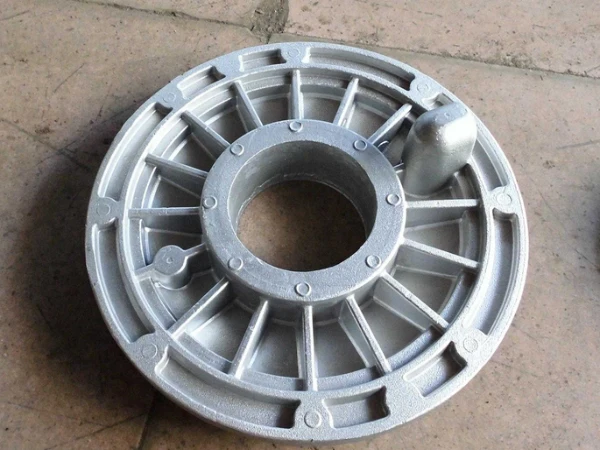
To maintain strict sand casting tolerances in complex, multi-component automotive assemblies, rigorous dimensional control must be exercised at every stage of production.
Achieving reliable sand casting tolerances requires in-depth expertise in predicting alloy shrinkage and managing the physical expansion of the mold during the pouring process. Since numerous casting variables can affect physical dimensions, it is essential to carefully calibrate positioning reference targets and positioning points relative to the mold parting line. By optimizing clamping pressure and maintaining strict fixture control, foundries can ensure that complex assemblies align precisely with CAD models, thereby minimizing dimensional deviations and preventing component mismatches on the assembly line.
Achieving strict sand casting tolerances in critical features
For critical mounting surfaces and structural locating points in automotive castings, it is essential to ensure consistency in sand casting tolerances. Maintaining tight tolerances within the ISO 8062 CT9 to CT11 range typically requires high-precision pattern-making equipment and highly dense sand molds. Since features spanning the parting line of the sand mold are susceptible to parting line deviations, critical reference points should be located within the same half of the mold whenever possible. This design minimizes mechanical deviations, thereby ensuring highly repeatable dimensional results in high-volume production.
Controlling mold shift and clamping pressure variables
Minimizing physical misalignment along the parting line of a sand casting is critical to maintaining the geometric symmetry of complex automotive castings. When the sand mold closes along the parting line, any misalignment between the upper and lower mold halves immediately results in dimensional errors. This issue is addressed by installing hardened steel guide pins on the mold assembly and applying calculated clamping counterweights or hydraulic tensioning devices. These measures counteract the immense buoyancy generated by the inflowing molten metal, preventing the mold from warping and thereby maintaining the accuracy of the casting’s cross-section.
Post-cast machining allowance planning across split lines
Planning the optimal machining allowance is a critical task in sand casting design, aimed at compensating for physical differences on either side of the mold parting line. Due to sand wear and mold assembly tolerances, slight dimensional accumulation naturally occurs on the parting surface in standard sand casting processes. This deviation is offset by adding a standardized machining allowance—typically ranging from 1.5 to 3.0 millimeters—to features that require CNC finishing after casting. This specifically reserved allowance ensures that cutting tools can thoroughly clean up critical surfaces without penetrating the dense casting skin.
Validating split line designs using prototype aluminum sand casting
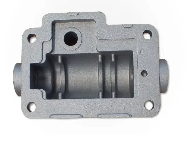
Before launching mass production, conducting a prototype aluminum sand casting trial is the industry-standard method for verifying the feasibility of complex sand mold parting lines. Through trial casting, the actual parting lines can be analyzed to verify whether the two halves of the sand mold can be securely assembled without dimensional misalignment. This provides rapid prototyping processes—such as 3D-printed sand molds or rapid wood pattern fabrication—with a method to quickly inspect the draft angle and draft transitions of prototypes under real casting conditions. By identifying and resolving gate anomalies on physical prototypes, critical mold geometries can be optimized, thereby ensuring a seamless scale-up to production and cost-effectiveness.
Fast tooling validation via prototype aluminum sand casting
Before investing in production molds, developing high-quality prototype aluminum sand casting is a critical physical test for verifying parting line coordinates.
The standard process for producing prototype aluminum sand casting involves using rapid mold-making methods to create high-precision test molds directly from 3D CAD files. These initial test pieces are then inspected to ensure that the draft angle allows for smooth demolding without damaging the mold walls. This rapid physical validation phase enables technicians to quickly adjust the parting lines of complex models, thereby avoiding costly mold redesigns and saving significant development time.
Analyzing metal flow and filling behavior in prototypes
Analyzing metal flow during sand casting trials is critical for identifying potential turbulence and cold-shut defects near the parting line. Preliminary casting trials help engineers observe how molten aluminum enters the mold cavity and fills the thin vertical walls along the mold parting line. By examining physical prototypes, casting technicians can precisely locate areas where bubbles are trapped or filling is incomplete due to inadequate venting at the parting line. This dynamic flow analysis ensures that the selected mold parting line does not disrupt the flow velocity or cause localized porosity.
Adjusting gating and riser configurations before scale production
Adjusting the runner layout in a prototype aluminum sand casting mold ensures that the pouring path is optimized prior to mass production. Through physical evaluation of the prototype aluminum sand casting, it is possible to determine whether the riser is correctly positioned relative to the parting line, thereby ensuring a sufficient supply of molten metal to thick-walled sections. If the prototype shows signs of shrinkage or porosity, the runner cross-section, gate, and vent holes must be redesigned promptly. Fine-tuning these pouring channels in the prototype mold ensures uniform metal distribution, resulting in dense, airtight automotive components that meet stringent quality standards.
Hľadáte spoľahlivú čínsku kovozlievareň?
- We can help you optimize product design and save costs.
- Môžeme vám pomôcť s vysokou kvalitou vo veľkom objeme odliatky.
- Dokážeme dodržať termíny a získať väčšie príležitosti na trhu predaja.
- Budete mať úžitok zo Supro MFG odlievanie kovov služba.
Contact Supro MFG
This paper systematically analyzes the principles for determining the sand casting parting line for automotive aluminum alloy components and its impact on casting quality. From geometric principles and flash control to cavity depth balancing and the setting of the sand casting draft angle, every step directly affects the achievement of sand casting tolerances and the control of post-processing costs. In practice, dimensional accumulation across the parting line is a common source of deviation, which must be offset by allowing for machining allowances and optimizing clamping force. Prototype aluminum sand casting trials can reveal metal flow and venting issues prior to mass production, serving as a critical step in adjusting sprue and gate configurations.
Leveraging its extensive engineering expertise in precision mold layout and parting line optimization, Supro MFG delivers highly repeatable, defect-free casting solutions that effectively reduce subsequent machining costs. Please contact Supro MFG to review your design and obtain the optimal mold layout strategy.
 English
 Čeština
 Français
 Deutsch
 Italiano
 日本語
日本語 한국어
한국어 فارسی
فارسی Polski
 Português de Angola
 Русский
 Slovenčina
 Español de Argentina
 Українська